Interface board V3
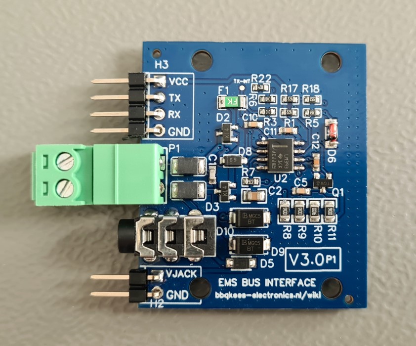
Available connectors on the V3.0 board
Number |
J# |
Function |
Remark |
|---|---|---|---|
1 |
P1 |
EMS screw terminal |
Polarity does not matter (in most cases). |
2 |
J3 |
EMS service jack plug |
Only connect either P1 or J3. |
3 |
H3 |
Controller UART header |
VCC/TX/RX/GND. Input 5V or 3.3V from controller. |
4 |
H2 |
8~16V pin from EMS service jack |
Left pin EMS 8~16V DC. Right pin GND. Max power draw 200mA cont. |
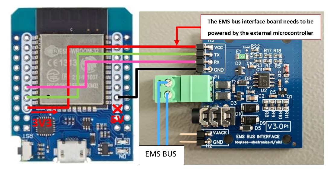
Connecting to the controller
The controller needs to power the interface board. Connect GND as well. Do not supply the interface board with more than 5V.
You can connect this board to any 5V or 3.3V compatible UART. This might be on an Arduino, ESP8266 or f.i. a Raspberry Pi. Connect header H3 to the controller.
Warning
The voltage on RX and TX follows the voltage of VCC. So if you connect the interface board to 5V, the GPIO pins of the microcontroller will also get 5V. This will kill the GPIO pins of f.i. an ESP32. Always use 3V3 for these chips.
Connect RX to the RX UART serial port and TX to the TX UART serial port of your controller. If you do not need TX you can just leave the pin unconnected.
See the following pages on how to connect the interface boards to specific microcontrollers.