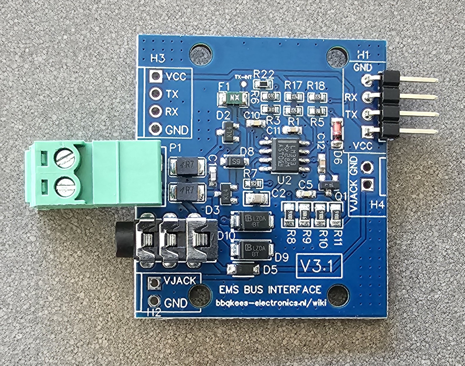
Interface board V3.1
The 3.1 version of the EMS interface board has the exact same EMS interface circuit as the 3.0 version. As an addition, the UART connector has been moved to the other side of the board. The footprint is still there on the left, so you can solder it there if you need it.
Available connectors on the V3.1 board
Number |
J# |
Function |
Remark |
|---|---|---|---|
1 |
P1 |
EMS screw terminal |
Polarity does not matter (in most cases). |
2 |
J3 |
EMS service jack plug |
Only connect either P1 or J3. |
3 |
H1/H3 |
Controller UART header |
VCC/TX/RX/GND. Input 5V or 3.3V from controller. |
4 |
H2/H4 |
8~16V pin from EMS service jack |
EMS 8~16V DC/GND. Max power draw 200mA cont. |
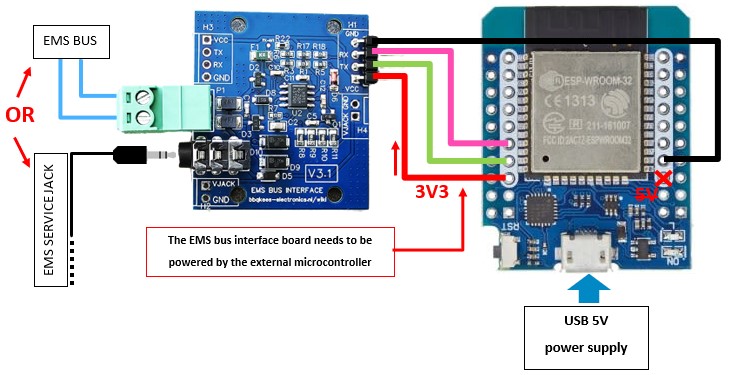
Connecting to the controller
The controller needs to power the interface board. This means if you f.i. connect an ESP32 development board to the EMS interface board, that you need to connect 3V3 from the ESP32 board to the interface board. Connect GND as well. Do not supply the interface board with more than 5V.
You can connect this board to any 5V or 3.3V compatible UART. This might be on an Arduino, ESP8266 or f.i. a Raspberry Pi. Connect the header H1 to the controller.
Warning
The voltage on RX and TX follows the voltage of VCC. So if you connect the interface board to 5V, the GPIO pins of the microcontroller will also get 5V. This will kill the GPIO pins of f.i. an ESP32. Always use 3V3 for these chips.
Connect RX to the RX UART serial port and TX to the TX UART serial port of your controller. If you do not need TX you can just leave the pin unconnected.
The header H1 has a soldered connector. H3 has the same pinout for those who need the connector on this side. H2 and H4 are also identical in pinout.
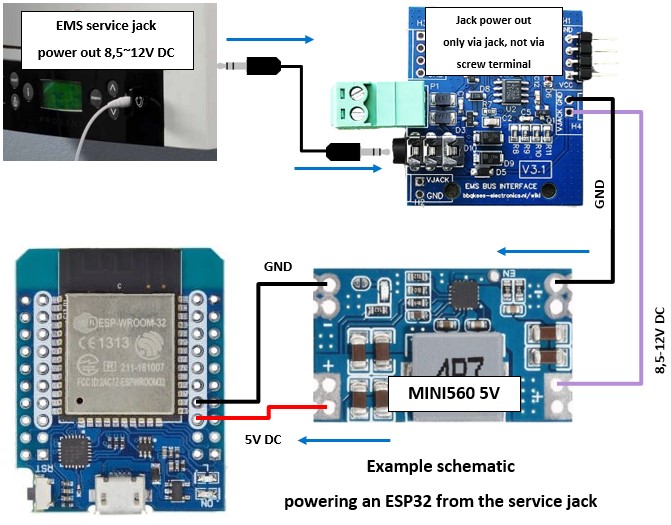
Drawing power from the service jack
The interface board also puts out the 8-12V pin of the EMS service jack via a header. This can be used to power small electronics via a decent buck type voltage regulator. (There will only be power on this pin if you use the service jack, the screw terminal does not have the third pin). If you do draw power from the EMS service jack make sure the 3.5mm jack cable you use can handle the current as most of these cables are meant for audio and therefore have very thin wires inside. Get an EMS service cable from the webshop for best results.
The best method to power external circuits from these pins is to use a buck converter. LDO’s will overheat pretty quickly due to the voltage difference. Also take care you do not short circuit the board in any way or feed this board with incorrect voltages as this may damage the board or the EMS bus. Also make sure the wires you connect the board to are in fact EMS bus wires and NOT 24V or mains power lines!!!!!!!!!
Warning
You cannot power an ESP32 development board directly from the jack. You will destroy the ESP32! You need to add a decent voltage regulator in between.
You are allowed to draw about of 200mA maximum from the service jack. This is enough for an ESP32 module and some sensors. However, do not attach more equipment like relays to the board. In that case power the module with a USB power supply.
See the following pages on how to connect the interface boards to specific microcontrollers.