Connecting a Gateway S3 (Standard edition)
The Gateway S3 and S3-LR have an external USB-C connector intended for firmware updates only. It is not intended to power the Gateway for prolonged amounts of time. Use only the supplied 12V DC barrel jack connector and/or the EMS service cable.
Preferred order of connection
In short this is the best order in which you should try to connect the Gateway:
Service jack (If your boiler has one).
If you have a solar or mixer module with a bus OUT: EMS bus wires on EMS OUT terminal of the module.
If you don’t have an external module use the same EMS bus screw terminal inside the boiler or heat pump (same as to which the EMS thermostat is connected or should be connected to).
The service jack provides enough power for the Gateway. In case you use the screw terminal also plug in the DC power supply. You do not need to use the DC power supply when you are using the service jack cable.
Service jack
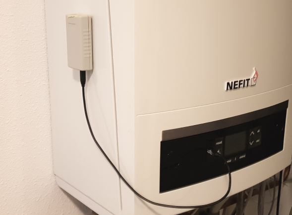
With the EMS service cable you can plug in the Gateway to the service jack of the boiler. The entire device is powered via this service jack. So no additional power supply needed. Just the jack cable is all you need.
On older boilers this service jack is usually located on the front near the display and the buttons, underneath a plastic or rubber flap. On the most recent boilers the service jack is usually found inside the boiler on the right or back side of the control module/display. On heat pumps this service jack is attached to a cable under neath the front cover of the inside unit.
Switch off the boiler or heat pump. First plug in the cable into the Gateway and then into the service jack on the boiler or heat pump. Press the plug firmly in the connector on both sides. Turn back on the boiler or heat pump. If the Gateway is plugged in correctly, it will start blinking to indicate it’s working and looking for the EMS bus and network.
Warning
Do not use cheap audio cables for connecting a Gateway to the service jack of the Gateway. Most of them have very thin wires inside, this may cause lots of interference and it is a possible fire risk. The EMS service cables from the webshop are high quality cables with thicker wires inside.
Note
If you plug in or unplug the jack cable from the Gateway first instead of the boiler side, you may momentarily shortcut the boiler. It will then reboot, which can cause some clicking noises. Nothing to worry about but just unplug the boiler side first.
Tip
If you have a thermostat like the RC310 and the display turns off when you plug in the Gateway via the service jack, reverse the two wires on the thermostat.
Note
Do not mount the Gateway inside the boiler or heatpump. It may get too hot for the Gateway, it will reduce WiFi reception and it possibly increases risk of fire.
EMS/thermostat wires
If your boiler does not have a service jack or it does but you want to mount the EMS Bus Gateway elsewhere you can use the screw terminal to connect to the two EMS bus wires.
Before doing any work, unplug the boiler or heat pump from power.
Please connect the ems screw terminal cable directly to the EMS screw terminal inside the boiler. In the EMS bus system try to maintain a star topology (so all EMS devices connect to the same screw terminal). You have to use the DC power supply when you are using the screw terminal.
In any case you need to follow the rules from Bosch regarding connecting a device to the EMS bus: - You need to use an (unshielded) cable with (at least) 2x0,5mm2 copper wire (Like the BBQKees EMS screw terminal cable). - In case of external inductive loads like a nearby PV installation, you need to use shielded wire.
Connect the shield to earth on one side only.
If there is already a device connected to the EMS bus, you need to add it in parallel.
NEVER connect any EMS device in serial on the same wires. If a EMS bus device has an ‘EMS OUT’ connector you may add a second EMS device there.
Maintain a so called ‘star topology’. This means that you connect every EMS bus device in parallel to the same EMS screw connector inside the heat source. (Of course adding an EMS bus device on the EMS OUT of another EMS bus device is still ok)
You need to use a minimum of 10cm of wire lenght for each EMS bus connection (in order to prevent reflections and collisions on the bus).
The S3 Gateway has a green external screw terminal.

On almost all boilers it does not matter which EMS wire you connect to which of these two terminal pins, as the Gateway has an internal correction circuit. However a few boilers and f.i. if you have an RC310 installed the orientation does matter. If installed the wrong way, the display of the thermostat will not show anything. If this is the case, just switch (so switch, not replace) both EMS wires on the Gateway in order to reverse polarity and if that does not work switch the EMS wires on the thermostat.
You can see here how to locate the correct EMS bus terminals on your boiler: Connecting the Gateway to the boiler or heat pump side.
If the Gateway is connected correctly, it will start blinking slowly to indicate it’s working and looking for the EMS bus and WiFi network.
Do not connect both the jack and the screw terminal at the same time. Both connectors are internally hardwired so by connecting both at the same time you can short circuit the bus.
First boot -> Check the LED
If you plug the Gateway into the boiler/heat pump or you connect the power plug, the blue LED will start to blink as a sign it has booted and looking for the EMS bus. As soons as it has discovered the EMS bus and your Wi-Fi network, it will light up solid. If the Gateway has already been configured before, the LED will light up solid really quickly after boot. But if it’s new and not connected to your WiFi network yet, it will continue to blink.
If the light is blinking, then go to Connecting the Gateway to your home network. If you don’t see any LED go to Troubleshooting.
During the power-on sequence you’ll see a sequence of LED flashes:
1 flash (slow blink) means the EMS bus is not connected
2 flashes means the network (wifi or ethernet) is not connected, but EMS is
3 flashes means both EMS bus and network are not connected.
A steady light after setup indicates a good network connection and EMS data is flowing in. However, if you are setting it up as new then the Gateway is not yet connected to your home network and therefore it will continue to blink twice.