How to connect the boards
Tip
Although you can connect the interface board to almost any microcontroller, my advice is to just don’t bother with any other platform than an ESP32 (or ESP32-S3) because without EMS-ESP you need to do all the low level decoding yourself. EMS-ESP has thousands of hours of work in it. You’ll never get anywhere near this. Better invest your time in learning about the EMS-ESP API if you need a custom implementation. You can use EMS-ESP on an ESP32 as a bridge between the EMS bus and your application. Also don’t bother with an ESP8266. The ‘old’ EMS-ESP V2 is not supported anymore.
The mimimum recommended specs of a module for EMS-ESP is an ESP32 or ESP32-S3 with 8MB FLASH and 2MB of PSRAM. More is always better. Letting EMS-ESP run on an ESP32 board without PSRAM will give poor results when connected to EMS systems with large amounts of entities like heat pumps.
General precautions and advise
If you are not comfortable with small electronics, wires that go everywhere, programming microcontrollers etc, then this EMS Interface board is not for you! Better buy an EMS Gateway instead, or if you already purchased an EMS Interface board, just return it for a refund and buy an EMS Gateway. EMS Gateways are intended to be plug and play devices that have decent designed electronics and pass all CE tests even in poor conditions. EMS Interface boards are also CE compliant, however anything you connect to it may not result in a CE compliant setup. It is your own responsibility to ensure the 10.000 Euro heat pump you are plugging your creative wire works into, won’t blow up because of your faulty wiring or thinking. That being said, tinkering with electronics is a exiting hobby for many and while doing so you learn a lot and you can achieve your intended goals for a bit less money.
Warning
We have tested a lot of ESP32 development boards from well known and respected manufacturers, and various boards from vague Chinese suppliers. Without test equipment they seem to run just fine obviously. However, as soon as you do a CE precompliance RF test, it becomes apparant that even the ‘better’ boards are spewing out noise on a broad range of frequencies. Our only recommendation (from what we tested) is the Espressif ESP32-Ethernet-Kit V1.2. Downside of this board is that it only has 4MB of Flash, which wont be enough soon for EMS-ESP.
Connecting to the controller
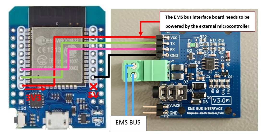
The controller (=ESP32 or other microcontroller board) needs to power the interface board. Connect GND as well. Do not supply the interface board with more than 5V.
You can connect this board to any 5V or 3.3V compatible UART. This might be on an Arduino, ESP8266 or f.i. a Raspberry Pi. Connect the header J2 to the controller.
Connect RX to the GPIO pin of the RX UART serial port and TX to the GPIO pin of the TX UART serial port of your controller (So do not connect RX to TX).
Tip
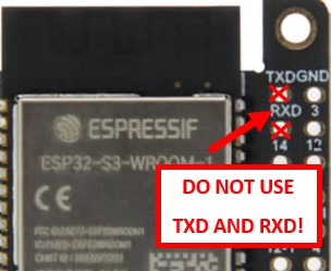
Most ESP32 development boards have pins marked RX and TX (or RX0, RDX and TX0, TXD). These pins are connected to the USB chip and cannot be used for the EMS interface board. In EMS-ESP, by default Rx is mapped to GPIO 23 and Tx is mapped to GPIO 5. We get daily emails from customers who can’t get their board to work because they used the TX0 and TX0 pins.
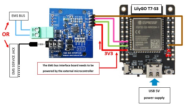
Liligo T7-S3
This module is the best WiFi-only option for using together with EMS-ESP.
Power the EMS board with 3.3V from the T7. Do not use the 5V pin as this will damage the I/O pins of the T7.
Pin on EMS board |
Pin on T7-S3 |
|---|---|
VCC |
3V3 (NOT 5V!) |
TX |
GPIO 5 |
RX |
GPIO 8 |
GND |
G or GND |
If you want to load EMS-ESP32 onto the module see the instructions on the EMS-ESP Wiki. Choose the S3 bin file with PSRAM enabled (+) and when configuring select the Liligo S3 board profile.
MH-ET Live D1 ESP32
Tip
If you start fresh with EMS-ESP it is advised to get a development board with the ESP32-S3 with PSRAM like the LilyGO T7-S3 instead of one of the ‘cheap’ ESP32 modules. The pinout of the T7-S3 is the same as the below MH-ET module.
Pin on EMS board |
Pin on D1 |
|---|---|
VCC |
3V3 (NOT 5V!) |
TX |
GPIO 5 |
RX |
GPIO 23 |
GND |
G or GND |
Tip
Some ESP32 development boards have pins marked RX and TX. These pins are connected to the USB chip and cannot be used for the EMS interface board. In EMS-ESP, by default Rx is mapped to GPIO 23 and Tx is mapped to GPIO 5.
If you want to load EMS-ESP32 onto the ESP32 see the instructions on the EMS-ESP Wiki.
WT32-ETH01
It is possible to connect the WT32-ETH01 board to the interface board, however it is the worst performing ESP32 board with Ethernet. And it does not have PSRAM, and only 4MB of Flash.
You need an external programmer to load EMS-ESP on it. You also need to power this module with 5V on the 5V pin. The module will then generate 3,3V for the interface board.
Pin on EMS board |
Pin on WT32-ETH01 |
|---|---|
VCC |
3V3 (NOT 5V!) |
TX |
GPIO 17 |
RX |
GPIO 5 |
GND |
G or GND |
In the EMS-ESP settings set the board profile to E32 and then the functions are as follows:
LED |
Dallas |
RX |
TX |
Button |
|---|---|---|---|---|
2 |
4 |
5 |
17 |
33 |
If you need Ethernet it is recommended to get the offical Espressif Ethernet board or f.i. an Olimex ESP32-WROVER like board instead of the WT32-ETH01. The WT32-ETH01 will not work reliably anymore with firmware 3.6.x or higher because it’s memory is too small.
Arduino
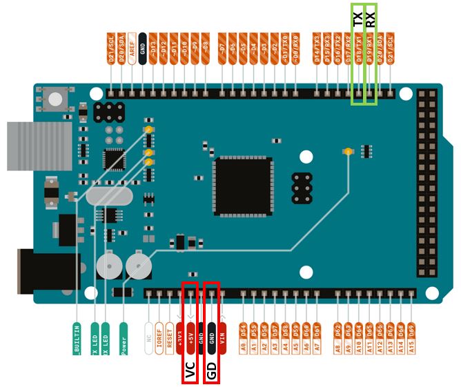
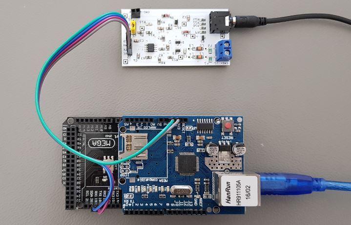
On the Arduino Mega 2560 in combination with the Github sketch connect RX to RX1 (pin 19) and TX to TX1 (pin 18). Connect VC to 5V and GD to GND. If you use an Arduino UNO you have no choice other than RX on pin 0 and TX on pin 1. In case you use the UNO do not connect the EMS board to the Arduino while you are programming the Arduino, because the same serial pins are used for programming the Arduino.
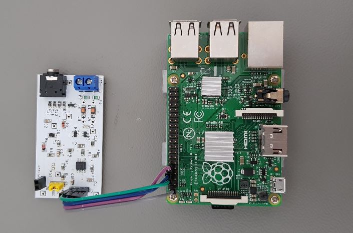
Raspberry Pi
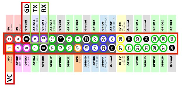
On the Raspberry Pi connect RX to GPIO 15 (pin 10) and TX to GPIO 14 (pin 8). Connect VC to 3V3 on pin 1 of the raspberry Pi header.
Warning: If you are using the Raspberry Pi header on the V1.0 board do not connect any 5V to the UART header!
Wemos D1 Mini (ESP8266)
Tip
Don’t bother with an ESP8266. The ‘old’ EMS-ESP V2 is not supported anymore. Use an ESP32 instead!
Pin on EMS board |
Pin on Wemos |
|---|---|
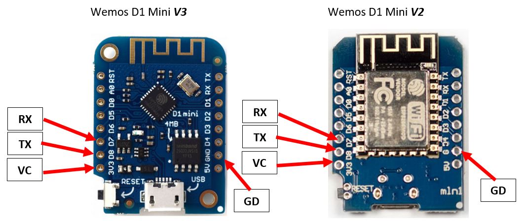
VC |
3V3 (NOT 5V!) |
TX |
D8 |
RX |
D7 |
GD |
G or GND |
Power the EMS board with 3.3V from the Wemos. Do not use the 5V pin as this will damage the I/O pins of the Wemos. The normal TX and RX pins on the Wemos are marked TX and RX, however for EMS-ESP this is set do D7 and D8. This is because the Wemos at boot sends debug information on TX and this disrupts the EMS bus.
Note
You can not run EMS-ESP32 on the ESP8266.
Drawing power from the service jack
The interface board also puts out the 8-12V pin of the EMS service jack via a header. This can be used to power small electronics via a decent buck type voltage regulator. There will only be power on this pin if you use the service jack, the screw terminal does not have the third pin. If you do draw power from the EMS service jack make sure the 3.5mm jack cable you use can handle the current as most of these cables are meant for audio and therefore have very thin wires inside. Get an EMS service cable from our webshop for best results.
The best method to power external circuits from these pins is to use a buck converter. LDO’s will overheat pretty quickly due to the voltage difference. Also take care you do not short circuit the board in any way or feed this board with incorrect voltages as this may damage the board or the EMS bus. Also make sure the wires you connect the board to are in fact EMS bus wires and NOT 24V or mains power lines!!!!!!!!!
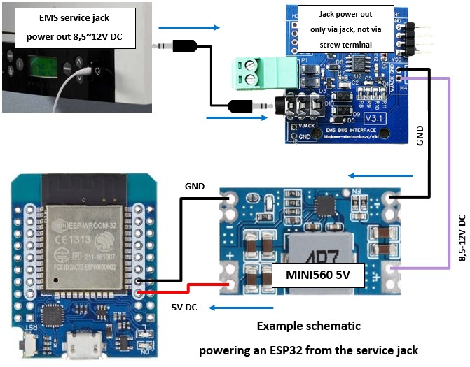
Warning
You cannot power an ESP32 development board directly from the jack. You will destroy the ESP32! You need to add a decent voltage regulator in between.
Drawing power from the EMS bus
The interface boards are not designed to draw power from the EMS bus itself. This is on purpose. There is no ‘parasitic’ mode. So you cannot power your microcontroller via the bus. Because of the way TX data transmissions work on the EMS bus, the circuit must be finetuned to a specific current draw of the electronics on the bus, otherwise it will not work. As the interface boards can be used with any microcontroller, they are designed so they can be safely used by all microcontrollers and are thus not tuned to a specific current. Furthermore drawing current from the EMS bus when there is also another EMS-bus-powered device on it like a thermostat, you will get all sorts of random connection issues.
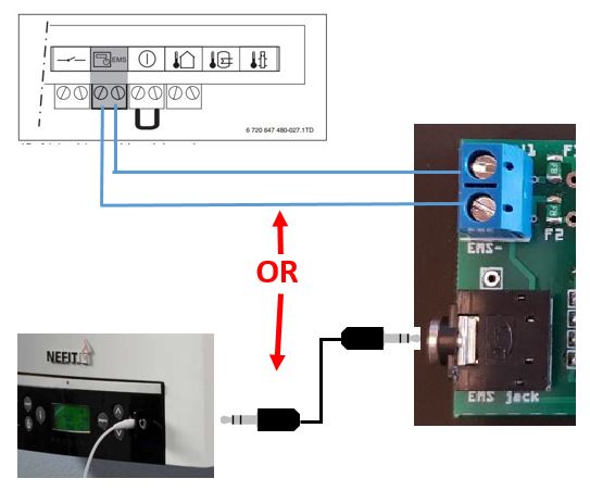
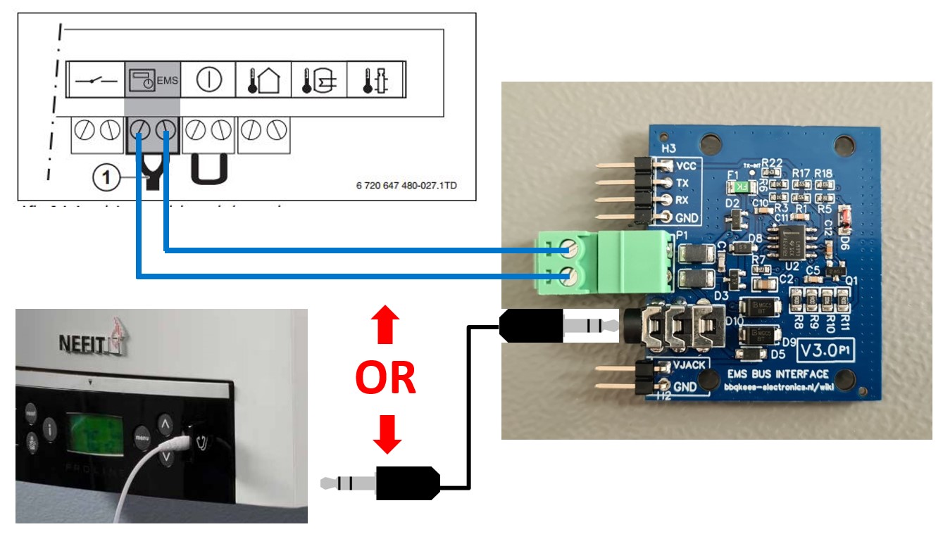
Connecting to the EMS bus
You can use EITHER the EMS bus service jack OR the screw terminal. Do not connect them at the same time, because you might short circuit the bus. If you use the screw terminal, polarity usually does not matter because the circuit bord corrects both orientations. In some cases polarity does matter. If the bus cannot be found, or the thermostat display gets empty or the boiler will give bus errors please switch the two EMS wires on the green screw terminal.
Warning
Do not use cheap audio cables for connecting a Gateway to the service jack of the Gateway. Most of them have very thin wires inside, this may cause lots of interference and it is a possible fire risk. The EMS service cables from the webshop are special high quality cables with thicker wires inside.
See some hints and tips for the EMS bus wiring here.