Connecting a Gateway E32 V2 (Ethernet + WiFi Edition V2)
Gateway connectors
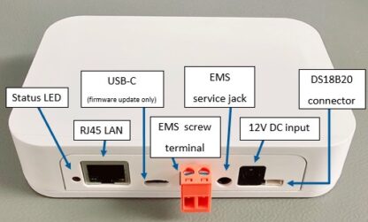
The Gateway E32 V2 has several connectors (from left to right):
RJ45 for LAN/Ethernet cable
USB-C port
EMS bus screw terminal (orange)
3,5mm EMS service jack connector
DC barrel jack connector (5.5/2.1mm)
JST connector (3-pin JST 1.5mm ZH)
The Gateway E32 V2 has an USB-C connector intended for firmware updates only. It is not intended to power the Gateway for prolonged amounts of time. (However some recent batches have a updated circuit board to allow 5V DC USB-C power as well. So if your order came with a USB-C power supply; don’t worry it is not a mistake)
E32 V2 Ethernet or WiFi
The E32 V2 has Ethernet for wired LAN, and WiFi for wireless LAN. The firmware supports one method to be active at a time. So it’s either wired LAN OR wireless LAN. The way this is dealt with in the firmware is that when anything is filled into the WiFi SSID or WiFi password field, Ethernet will be disabled. So if you have setup the Gateway to connect to your home network via WiFi, the Ethernet port will stay disabled, even when you insert a LAN cable. If the Gateway has not been configured yet, plugging in an Ethernet cable into the RJ45 port of the Gateway will create a wired LAN connection immediately. If you have configured the Gateway to work via WiFi, and you want to use Ethernet instead, you need to login to the web interface of the Gateway and clear both the SSID and password fields. Then save and reboot. Only then the Ethernet port will become active.
Gateway LEDs
The EMS Gateways have 3 seperate LEDs to indicate the status of the Gateway and the status of the Ethernet/wired lan port.
Gateway status LED
The Gateway has a status indicator LED left of the LAN port. All E32 V2 Gateways until summer 2025 have a blue status LED. Most E32 V2 Gateways from summer 2025 onwards have a multi-color RGB LED.
For Gateways with a blue LED:
1 flash (slow blink) means the EMS bus is not connected
2 flashes means the network (wifi or ethernet) is not connected, but EMS is
3 flashes means both EMS bus and network are not connected.
A steady light after setup indicates a good network connection and EMS data is flowing in. However, if you are setting it up as new then the Gateway is not yet connected to your home network and therefore it will continue to blink twice. If you have plugged in a LAN cable it will blink once, and if you also already plugged it into the EMS bus it will light up solid.
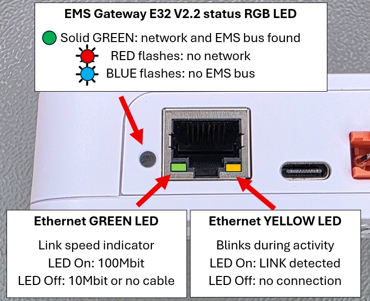
For Gateways with a RGB multi-color LED:
Steady GREEN means both the EMS bus and network (either wired or wireless) is connected.
BLUE light blinking means the EMS bus has not been found.
RED light blinking means no network has been found.
RED and BLUE may be both blinking as an alternating pattern. This means that neither the EMS bus nor network has been found or connected.
RJ45 Ethernet connector LEDs
The Ethernet port itself also has two LEDs. These LED’s are seperate from the Gateway status LED. Left LED (Green): This LED turns on when there is a 100Mbit connection with the network. If off, the link speed is 10Mbit. Right LED (Yellow): This LED is on when a network link has been detected. It also blinks during activity. If both LED’s are off when a LAN cable is connected, the LAN port is not active. You may need to activate it in the firmware. See further down below.
General precautions
For a lot of boilers and heat pumps, you have to remove the cover to access the EMS bus terminals. Before you open it up, always disconnect the heat source from power if possible. There is mains voltage present near the EMS bus terminal. So be careful. If you do not feel comfortable connecting a Gateway, ask someone else or a professional installer.
Furthermore as the boiler or heat pump is a heat source, some of the internal components may get very hot obviously.
Most information about connecting the Gateway to your boiler or heat pump is repeated on the following pages, because it is important you do this correctly.
Preferred order of connection to the EMS bus
In short this is the best order in which you should try to connect the Gateway:
Service jack (If your boiler or heat pump has one).
If you have a solar or mixer module with a bus OUT: EMS bus wires on EMS OUT terminal of the module.
If you don’t have an external module use the same EMS bus terminal as to which the thermostat is connected or should be connected to.
The service jack provides enough power for the Gateway. In case you use the screw terminal also plug in the DC power supply. You do not need to use the DC power supply when you are using the service jack cable. However the service port on the boiler/heat pump will lose power for a short while when the heat source is restarted. In this case the Gateway will also restart. Connecting the power supply will prevent this.
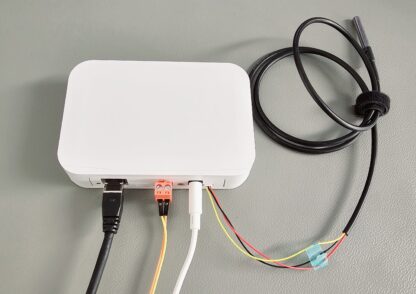
Service jack
With the EMS service cable you can plug in the Gateway to the service jack of the boiler or heat pump. The entire device is powered via this service jack. So no additional power supply needed. Just the jack cable is all you need.
On older boilers this service jack is usually located on the front near the display and the buttons, underneath a plastic or rubber flap. On the most recent boilers the service jack is usually found inside the boiler on the right or back side of the control module/display. On heat pumps this service jack is attached to a cable under neath the front cover of the inside unit.
Switch off the boiler or heat pump. First plug in the cable into the Gateway and then into the service jack on the boiler or heat pump. Press the plug firmly in the connector on both sides. Turn back on the boiler or heat pump. If the Gateway is plugged in correctly, it will start blinking to indicate it’s working and looking for the EMS bus and network.
Warning
Do not use cheap audio cables for connecting a Gateway to the service jack of the Gateway. Most of them have very thin wires inside, this may cause lots of interference and it is a possible fire risk. Use only EMS service cables from the webshop. These are high quality cables with thicker wires inside.
Note
If you plug in or unplug the jack cable from the Gateway first instead of the boiler side, you may momentarily shortcut the boiler. It will then reboot, which can cause some clicking noises. Nothing to worry about but just unplug the boiler side first.
Tip
If you have a thermostat like the RC310 and the display turns off when you plug in the Gateway via the service jack, reverse the two wires on the thermostat.
Note
Do not mount the Gateway inside the boiler or heatpump. It may get too hot for the Gateway, it will reduce WiFi reception and it possibly increases risk of fire.
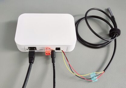
EMS/thermostat wires
If your boiler does not have a service jack or it does but you want to mount the EMS Bus Gateway elsewhere you can use the screw terminal to connect to the two EMS bus wires. Please connect the ems screw terminal cable directly to the EMS screw terminal inside the boiler. In the EMS bus system try to keep a star topology (so all EMS devices connect to the same screw terminal). Do not use shorter cables than 10cm. You have to use the DC power supply when you are using the screw terminal.
See some hints and tips for the EMS bus wiring here.
The Gateway has an orange external screw terminal.
On almost all boilers it does not matter which EMS wire you connect to which of these two terminal pins, as the Gateway has an internal correction circuit. However a few boilers and f.i. if you have an RC310 installed the orientation does matter. If installed the wrong way, the display of the thermostat will not show anything. If this is the case, just switch (so switch, not replace) both EMS wires on the Gateway and if that does not work switch the EMS wires on the thermostat.
You can see here how to locate the correct EMS bus terminals on your boiler: Connecting the Gateway to the boiler or heat pump side.
If the Gateway is connected correctly, it will start blinking to indicate it’s working and looking for the EMS bus and (WiFi) network.
Do not connect both the jack and the screw terminal at the same time. Both connectors are internally hardwired so by connecting both at the same time you can short circuit the bus.
First boot -> Check the LED
If you plug the Gateway into the boiler/heat pump or you connect the power plug, the Gateway LED will start to blink as a sign it has booted and looking for the EMS bus. As soons as it has discovered the EMS bus and your Wi-Fi/LAN network, it will light up solid. If the Gateway has already been configured before, the LED will light up solid really quickly after boot. But if it’s new and not connected to your WiFi network yet, it will continue to blink.
If the light is blinking, then go to Connecting the Gateway to your home network. If you don’t see any LED go to Troubleshooting.
During the power-on sequence you may see a sequence of any of the following LED flashes:
For Gateways with a blue LED:
1 flash (slow blink) means the EMS bus is not connected
2 flashes means the network (wifi or ethernet) is not connected, but EMS is
3 flashes means both EMS bus and network are not connected.
A steady light after setup indicates a good network connection and EMS data is flowing in. However, if you are setting it up as new then the Gateway is not yet connected to your home network and therefore it will continue to blink twice. If you have plugged in a LAN cable it will blink once, and if you also already plugged it into the EMS bus it will light up solid.
For Gateways with a RGB multi-color LED:
Steady GREEN means both the EMS bus and network (either wired or wireless) is connected.
BLUE light blinking means the EMS bus has not been found.
RED light blinking means no network has been found.
RED and BLUE may be both blinking as an alternating pattern. This means that neither the EMS bus nor network has been found or connected.