Interface board V0.9
This board was the actual first product that started it all.
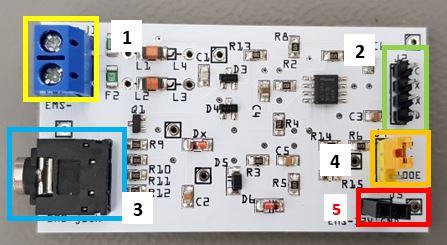
Available connectors on the V0.9 board
Number |
J# |
Function |
Remark |
|---|---|---|---|
1 |
J1 |
EMS screw terminal |
Polarity does not matter. |
2 |
J2 |
Controller UART header |
VCC/TX/RX/GND. Input 5V or 3.3V from controller. |
3 |
J3 |
EMS service jack plug |
Only connect either J1 or J3. |
4 |
J4 |
RX resistor selector |
Select either 4k7 or 100E resistor. |
5 |
J5 |
8~16V pin from EMS service jack |
Left pin EMS 8~16V DC. Right pin GND. Max power draw 200mA cont. |
Connecting to the controller
The controller needs to power the interface board. Connect GND as well. Do not supply the interface board with more than 5V.
You can connect this board to any 5V or 3.3V compatible UART. This might be on an Arduino, ESP8266 or f.i. a Raspberry Pi. Connect the header J2 to the controller. For the V0.9 board use the jumper of J4 to select the correct RX UART resistor setting. For most Arduino’s and the Pi this is setting 1. This setting provides a standard 4k7 Ohm resistor on the output. For the ESP8266 use setting 2. Setting 2 provides a 100 Ohm resistor on the output, specifically intended for the ESP8266 and other similar chips. If one particular setting does not work, try the other setting too. Connect RX to the RX UART serial port and TX to the TX UART serial port of your controller. If you do not need TX you can just leave the pin unconnected.
Warning: If you are using the Raspberry Pi header on the V1.0 board do not connect any 5V to the UART header!
See the following pages on how to connect the interface boards to specific microcontrollers.