EMS bus wiring
Using the service jack
If your boiler or heatpump has a service jack, just connect the Gateway with the EMS service cable. The service jack has pins for both the EMS bus and an additional power supply for peripherals. You do not need to add an external power supply in this case. You can get a very high quality EMS service cable from the webshop. This cable has the proper wire diameter inside which is necessary for also powering the Gateway. Furthermore the cable has extended plugs, so it will fit into the recessed holes of certain boiler als also into the recessed hole of the E32 V2.
Warning
Do not use cheap audio cables for connecting a Gateway to the service jack of the boiler/heatpump. Most of them have very thin wires inside, this may cause lots of interference and it is a possible fire risk. The EMS service cable from the webshop is a high quality cable with thicker wires inside.
Splitting service jack power
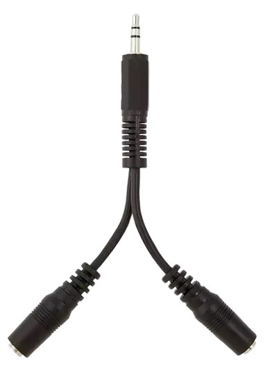
If you have f.i. a KM50 module already on the service jack, then you can split the jack connector with a 3,5mm audio splitter. This method is not recommended and it may not always work, but you can try. Use a high quality connector type splitter and not one with long cables attached as these cables are intended for audio and thus have very thin wires inside. Turn off the Gateway/KM50/boiler, connect them all and them turn on the boiler again.
If the KM50 or the Gateway does not work via the splitter cable, you need to remove the splitter and connect the Gateway to the BUS terminal and add an external power supply.

Using the EMS screw terminal
If you want to use the screw terminal on the Gateway, you need to connect a cable with two wires between the screw terminal of the Gateway to the EMS terminal inside the boiler (usually an orange or white connector). If there is already something attached to the EMS terminal in the boiler / heat pump, you can connect the Gateway in parallel on that connector. Do not connect other bus participants to the screw terminal of the Gateway.
According to Bosch, the total length of cable between all EMS participants on the same bus is:
100m for 0,50 mm2 wire.
300m for 1,50 mm2 wire.
Furthermore there are some additional requirements to adhere to:
If several EMS bus participants are installed, they must be have a minimum distance of 100 mm between each other.
If several EMS bus participants are installed, they must be connected in series or star-shaped. Do not create a ring topology.
With external inductive influences (e.g. from photovoltaic systems) use shielded cable. Ground the shielding on only one side of the housing.
So in a practical situation you have at least several dozens of meters available.
It does not matter here if it is solid or stranded wire.
For connecting a Gateway, if you run up to several meters of cable length, an unshielded cable with 2x0,5 mm2 conductors is more than sufficient.
Alternatively you can f.i. use a piece of left over Ethernet cable where you combine two conductors for each EMS pin. If the cable has shielding, only connect the shielding to the boiler/heat pump side. Do not connect any shielding to the EMS bus pins or other parts of the Gateway.