Adding external temperature sensors
Each Gateway has an additional connector for connecting external temperature sensors with a digital one-wire bus. The one-wire bus is used with the very popular DS18B20 temperature sensors which are available at low cost everywhere.
Supported sensors
Sensors supported are of the Dallas types (All Gateways except E32 V2.2):
DS1822
DS18S20
DS18B20
DS1825
Sensors supported are of the Dallas type (Only Gateway E32 V2.2): - DS18B20 in non-parasitic mode
Multiple sensors can be connected to the connector at the same time and they can be run in either normal or parasitic mode. (E32 V2.2 only non-parasitic). You can connect several sensors (of the same type only) in parallel with various lenghts. EMS-ESP has no real practical upper limit for the amount of sensors you can connect simultaneously. Some users are reporting using 10 or more sensors with various lenghts of cable.
Connecting sensors
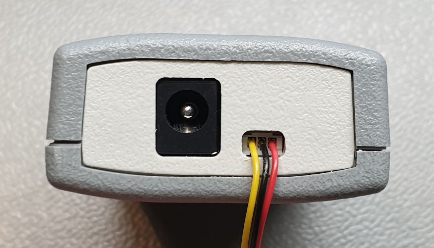
On the side of the Gateway you can find a small white 3-pin JST connector. If you purchased a Gateway a JST cable was included. If you have lost or broke it you can contact us or get a cable yourself. They are very cheap on f.i. AliExpress. You need a three-wire JST ZH (1.50mm) cable for the Gateway S32, S3, E32 and E32 V2/V2.2.
The colors on the cable match the colors on generic waterproof three wire BS18B20 sensors. (Schematics see further below)
Gateway type |
Yellow (left pin) |
Black (middle pin) |
Red (right pin) |
|---|---|---|---|
E32 V2.2, E32 V2, E32, S3, S3-LR, S32 |
Data |
GND |
3V3 |
Warning
If you make a mistake and shortcut the GND and Data pin, you will shortcut the internal Gateway power. In this case the Gateway will shutdown, except for the E32 V2 with V2.2 board. If you draw too much current from 3V3 the Gateway will stop functioning correctly. Only the E32 V2.2 has a 100mA current limiting protection on this connector. DO not connect anything else than one-wire temperature sensors to the JST connector as the Gateway has not been designed for this.
Gateway E32 V2 and E32 V2.2
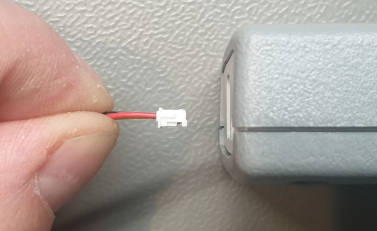
The Gateway E32 V2 and E32 V2.2 have a small JST ZH connector (It’s the connector on the far right). The colors on the cable match the colors on the Dallas sensor wires (But please check pinout of your cable).
First unplug the Gateway from bus and power.
Connect the sensors to the cable and insert it into the Gateway. It will only fit in one orientation.
When you insert the cable, press it fully inwards with a pen or screwdriver.
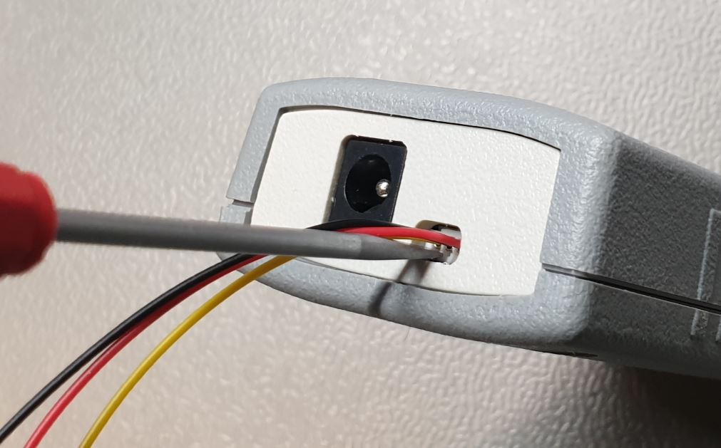
The cable is not designed for a lot of unplugging, so be careful.
After you have connected the sensor(s), connect power and bus to the Gateway and go to the web interface. See below.
Note
The E32 V2.2 board already has an DS18B20 sensor mounted on the circuit board to measure the temperatue inside the housing. It is a DS18B20(S) sensor on the same one-wire bus which does not use parasitic mode. So for this model you cannot use parasitic mode. If you really need parasitic mode, send us an email to discuss the modification needed.
Gateway S32 and E32
The Gateway S32 and the E32 have a small JST ZH connector. The colors on the cable match the colors on the Dallas sensor wires.
First unplug the Gateway from bus and power.
Connect the sensors to the cable and insert it into the Gateway. It will only fit in one orientation.
When you insert the cable, press it fully inwards with a pen or screwdriver.
The cable is not designed for a lot of unplugging, so be careful.
After you have connected the sensor(s), connect power and bus to the Gateway and go to the web interface. See below.
Sensor pull up resistor
The one-wire bus needs a pull-up resistor. On every Gateway board there is a 4k7 resistor between the data pin and 3V3. For most cases this pull-up on the board is sufficient. However, if you connect too many sensors or the wires are very long, the pull-up resistor value may be to high. Depending on the Gateway you can add an external resistor (recommended) or add a internal resistor (not recommended).
This optional resistor will be connected in parallel with the internal 4K7 resistor. Recommended in that case is to use a 4K7 resistor, so the final resistor value will be 2K35.
You can insert an external resistor in a screw connector so it directly attaches to the yellow and red wires outside of the Gateway. You can solder one or more DS18B20 sensors to the JST cable or use f.i. a screw terminal.
Please be advised (waterproof) DS18B20 sensors from AliExpress etc are almost never genuine Dallas sensors and can have an offset of sometimes 2 degrees Celcius. You can trim the sensor by adding a temperature offset via the web interface of the Gateway. 00 Resistor location Gateways ————————–
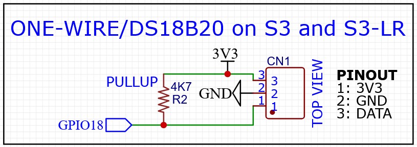
The S3 and S3-LR use the same circuit board.
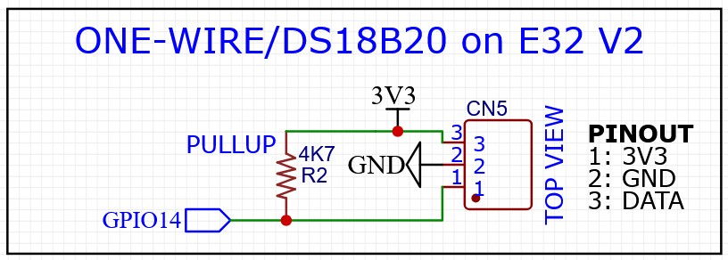
The E32 V2 and E32 V2.1 board have the following schematic:
The schematic of the one-wire bus circuit on the E32 V2.2 board looks like the equivalent below:
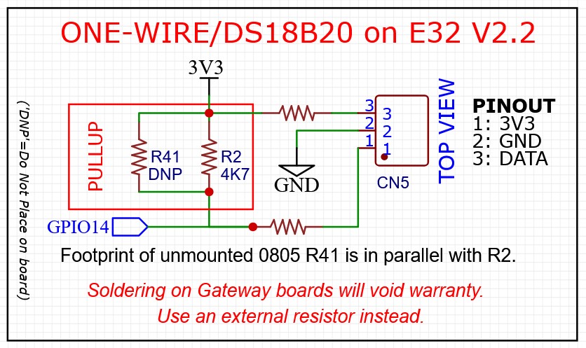
On this board 0805 resistor footprint R41 is not populated (DNP). R41 is in parallel with R2. Adding f.i. a 4K7 resistor here will result in a pullup value of 2K35.
Note
Please only add external resistors to the circuit. Soldering on any Gateway board will void warranty. As already mentioned above there is already a DS18B20 sensor mounted on the V2.2 circuit board.
Gateway configuration
After adding the sensors, reboot the Gateway and go to the Devices and Sensors tab of the web interface.
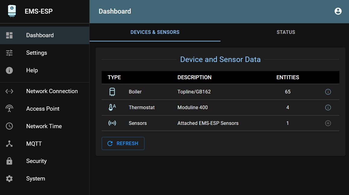
You should now see new devices in ‘Sensors’. If you can’t see new Sensors, then the Gateway has not detected the sensors. Check the wiring. If wired correctly, you should see an entry for each sensor.
To find out which sensor is which, hold it in your hand or heat it up otherwise individually to see in the dashboard which of the sensors is heating up. If needed you can add a temperature offset for a particular sensor.
You can always add more sensors later, EMS-ESP remembers which sensor is which.
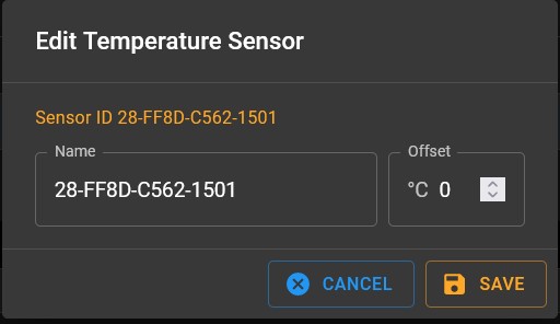
Renaming sensors and offset
You can rename sensors by clicking on the pen icon next to the sensor ID.
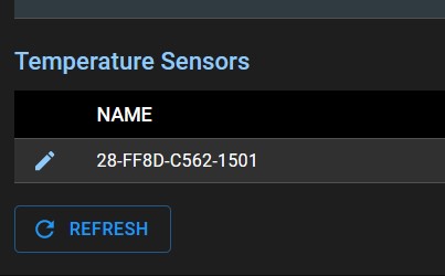
In the popup that appears you can change the sensor name and add a temperature offset is needed.