Connecting the Gateway to the boiler or heat pump side
You can connect the Gateway to either the service jack of the boiler or heatpump (if it has one). or you can connect it to the EMS bus wires on the inside of the boiler/heat pump or on the OUT side of a mixer or solar module.
Note
For most hybrid system consisting of an EMS gas boiler and an EMS heat pump, you can connect the Gateway to either the boiler OR the heat pump. Because of a technical limitation of the EMS bus, if you connect the Gateway to the boiler, you cannot see the heatpump and vice versa. Only hybrid systems with a hybrid manager like the Bosch MH200/MH310 allow the boiler to be seen from the heat pump bus.
Service jack
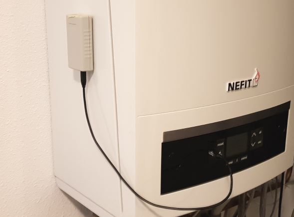
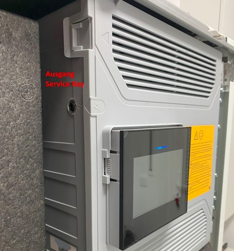
With the EMS service cable you can plug in the Gateway to the service jack of the boiler or heat pump. This is usually located on the front of the boiler below a rubber or plastic flap. 5000i/8000/9000i models and all heat pumps have the service jack under the front cover. |br| The service jack for heat pumps is often hidden away as a seperate cable inside the housing. The entire device is powered via this service jack. So no additional power supply needed. Just the EMS service cable is all you need.
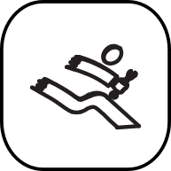
The service jack on a boiler or heat pump usually has one of the two following icons next to it. Older boilers have a stethoscope icon, and all newer boilers and heatpumps have the ‘running service man (or woman)’ icon. The logo is often embossed in the plastic next the the service jack.

Warning
Do NOT use cheap audio cables for connecting a Gateway to the service jack of the Gateway. Most of them have very thin wires inside, this may cause lots of interference and it is a possible fire risk. The EMS service cable from the webshop is a custom high quality cable with thicker wires inside.
Switch off the boiler or heat pump. First plug in the cable to the Gateway and then into the boiler or heat pump. Press the plug firmly in the connector or both sides. Turn on the boiler or heat pump. If the Gateway is plugged in correctly, it will start blinking slowly to indicate it’s working and looking for the EMS bus and WiFi network.
Below some examples of service jack locations.
Note
Do not mount the Gateway inside the boiler or heatpump. It may get too hot for the Gateway, it will reduce WiFi reception etc.
Service jack on boilers
There are more possible locations, but not all boilers have a service jack. In general ALL Nefit boilers, most Buderus and Bosch boilers, and some Junkers boilers have a service jack. Most new Bosch boilers have one, even if it is not mentioned in the documentation.


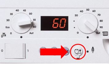
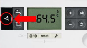
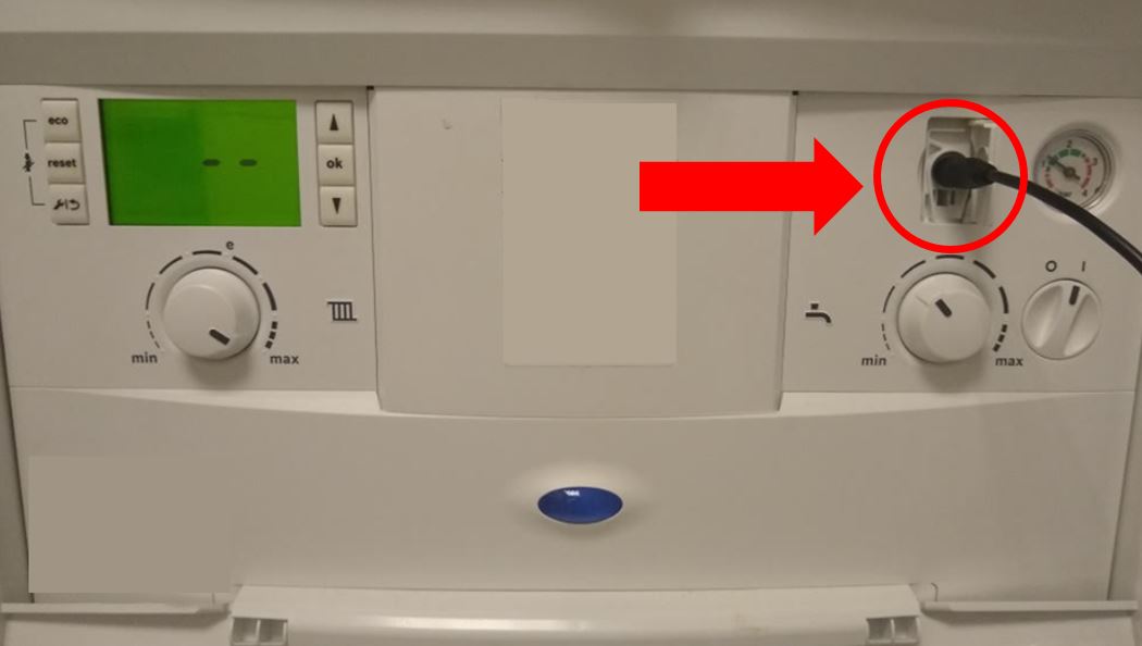
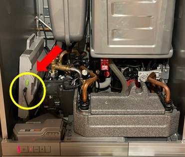
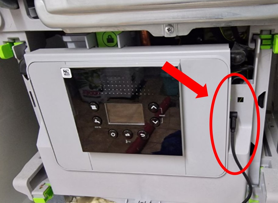

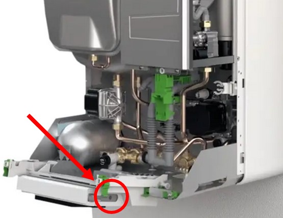
All Nefit boilers have the service jack on the front of the boiler, most new Bosch models have the service jack under the front cover either on the right of the display or the below left inside the boiler. If there is already a device attached to the service jack (like a MB LAN or KM100) you need to connect the Gateway via the green screw terminal (Splitting the service jack is not recommended).
Service jack on heat pumps
Almosty all heat pumps have the service jack as a cable inside the housing (It is recommended to not stick the whole Gateway inside but use the longer 110cm EMS cable to route it outside of the housing). This cable may be hidden away behind other cables.
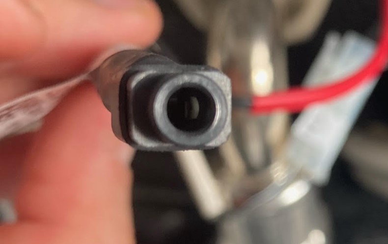
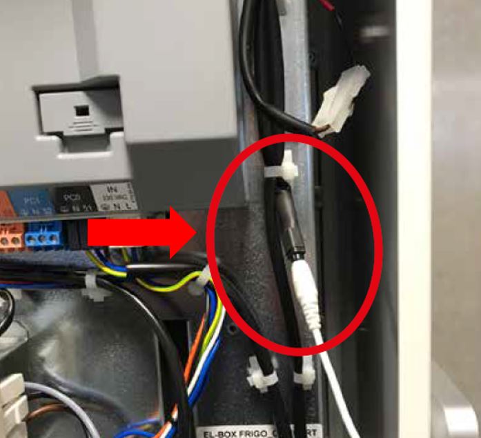
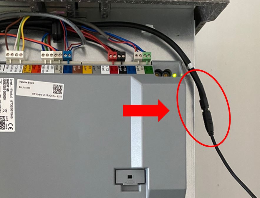
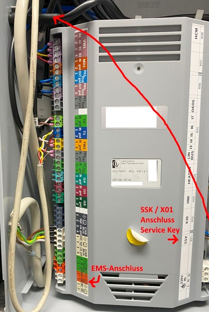
The cable starts from the white BBT connector on the side of the grey installer board.
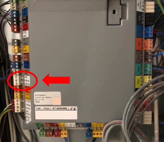

The latest heat pumps have a different installer board. Here the cable comes from the SSK connector. Some also have the jack mounted on the side of the plastic housing like below.

Note
The grey boxes with all connectors as seen in the images above are called an ‘installer board’. Most Bosch heat pumps with an EMS bus have one of these exact same boards. If your heat pump does not have one, your heat pump may be one of the few that has no EMS at all. Please contact me in that case, you may have to return the Gateway.
For some boiler models and some heat pump models it is not possible to close the front cover with the EMS service cable inserted. In these cases you need to use the EMS service port adapter as shown below.


Tip
If your Gateway is connected with the (relatively short) EMS service cable, but does not have suitable WiFi reception where it is mounted, you can relocate the Gateway to a position with better reception. You can do this by connecting the Gateway via the two-wire EMS bus screw terminal. The EMS bus allows quite long wires, f.i. 10m is not an issue.
EMS/thermostat wires
If your boiler does not have a service jack or it does, but you want to mount the EMS Bus Gateway elsewhere you can use the screw terminal to connect to the two EMS bus wires. This can be in parallel with the thermostat or other EMS devices on the same screw terminal from inside the boiler.
Note
Try to maintain a star topology. This means all EMS devices have their own cable directly on the same EMS screw terminal. Do not use cables shorter than 10cm.
Inside the boiler there is a row of electrical screw terminals which will resemble something like the examples below. There might be a short row of terminals but for some boilers there might be 20 terminals or more.
Danger
Be careful when accessing the inside of the boiler or heat pump. Mains voltage is present. Always unplug the boiler from the mains voltage before continuing. Also the inside of the boiler or heat pump maybu be hot, as you might expect from a heat source.


Now you need to find the EMS bus terminal connector. Usually this connector is orange or white for boilers and modules, and blue for heat pumps. It will say ‘BUS’, ‘EMS’, or it has an icon of a thermostat. If your boiler has an EMS thermostat connected, it will also be connected to this terminal. For some Junkers boilers the terminals are green and marked ‘B’ and ‘B’, or ‘RC’.
Tip
If you have a Junkers boiler and you see that your thermostat (all of FR/FW 50/100/110/120 etc) is not on the BB connectors but on three other connectors (1/2/4) next to it you can rewire the thermostat to the two pin BB connector as well. Otherwise the thermostat cannot be seen on the EMS bus. Remove the thermostat from the wall bracket and se which wires are on BB and connect these to BB on the boiler side as well.
Below a number of possible EMS bus connector types from several boiler models.
On the next page there is also a more detailed guide with examples on many specific boilers and heatpumps. See: Connecting the Gateway to specific boilers and heatpumps.

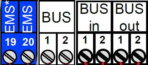
If your boiler has multiple EMS bus connectors, connect the Gateway to the orange/blue one or to a connector which is already wired to an EMS bus device. If your EMS module has both an EMS IN and EMS OUT connector, first try out EMS OUT and if that does not work use the EMS IN. If your EMS module has multiple numbered EMS bus connectors, connect the Gateway to the EMS bus connector that is orange or to the connector that has no number.
Warning
DO NOT connect the Gateway to an on/off contact, an OpenTherm bus, a 24V or mains line! ONLY to an EMS bus connector. Do not connect the Gateway in series with other EMS devices, only in parallel. If you are unsure which connector to use, send me a picture and I’ll help you selecting the correct one.
Below some ‘forbidden’ connectors:

On almost all boilers it does not matter which EMS wire you connect to which of these two terminal pins, as the Gateway has an internal correction circuit. However a few boilers and f.i. if you have an RC310 installed the orientation does matter. If installed the wrong way, the display of the thermostat will not show anything. If this is the case, just switch (so switch, not replace) both EMS wires on the Gateway and if that does not work switch the EMS wires on the thermostat.
If the Gateway is connected correctly, it will start blinking slowly to indicate it’s working and looking for the EMS bus and WiFi network.
Do not connect both the jack and the screw terminal at the same time. Both connectors are internally hardwired so by connecting both at the same time you can short circuit the bus.
First boot -> Check the LED
If you plug the Gateway into the boiler or you connect the power plug, the blue LED will start to blink as a sign it has booted and looking for the EMS bus. As soons as it has discovered the EMS bus and your Wi-Fi network, it will light up solid. If the Gateway has already been configured before, the LED will light up solid really quickly after boot, or it will blink slowly. But if it’s new and not connected to your WiFi network yet, it will continue to blink.
If the light is blinking, then go to Connecting the Gateway to your home network. If you don’t see any LED go to Troubleshooting.
During the power-on sequence you’ll see a sequence of LED flashes:
1 flash means the EMS bus is not connected, but the network is.
2 flashes means the network (wifi or ethernet) is not connected, but EMS is.
3 flashes means both EMS bus and network are failing.
A steady light indicates a good connection and EMS data is flowing in. A slow pulse can mean either the WiFi or the EMS bus are not connected yet. A very fast pulse is when the system is booting up and configuring itself which can typically takes a few seconds. If the LED is off, either the Gateway is turned off, has a wrong board profile or the LED is turned off in the settings.