When you want to update via USB or you need to load a specific firmware version on your BBQKees Gateway, you have to upload the correct bin file to your Gateway or otherwise you may brick it.
For uploading a new firmware to your Gateway via USB you need to use the EMS-ESP flash tool. See the wiki here for more instructions. In some cases you can manually download the firmware, and upload it via the web interface of the Gateway.
On the EMS-ESP Github repository you can download the firmware bin files. The naming convention since firmware 3.6.5 is structured according to the chip type (chipset) and features, and does not have the name of a Gateway product in it.
It is structured like below:
EMS-ESP-<version>-<chipset>-<flashsize>[+].bin
where <chipset> is ESP32 or ESP32S3 and <flashsize> either 4MB or 16MB. The + indicates that the firmware is built to use any additional RAM (called PSRAM) if available.
See the EMS-ESP download info page here for more information.
If you want to upload a specific firmware version 3.7.2 to lets say a new E32 V2 Gateway, you first need to lookup which ESP32 chip is used. The E32 V2 has a ESP32 chipset with 16MB of Flash and 8MB of PSRAM. The filename of the bin file would then be EMS-ESP-3_7_2-ESP32-16MB+.bin.
Below a handy list about which Gateway model has which features and thus needs which firmware bin file.
So firmware version 3.7.2 for the EMS Gateway E32 V2 is this one:
https://github.com/emsesp/EMS-ESP32/releases/download/v3.7.2/EMS-ESP-3_7_2-ESP32-16MB+.bin
As a second example say you would like to get the 3.7.1 firmware for the S3 Gateway.
That’s the following bin file:
https://github.com/emsesp/EMS-ESP32/releases/download/v3.7.1/EMS-ESP-3_7_2-ESP32S3-16MB+.bin
| Model | Side image | ESP32 chip type | Flash storage | PSRAM storage | Firmware name ends with |
|---|---|---|---|---|---|
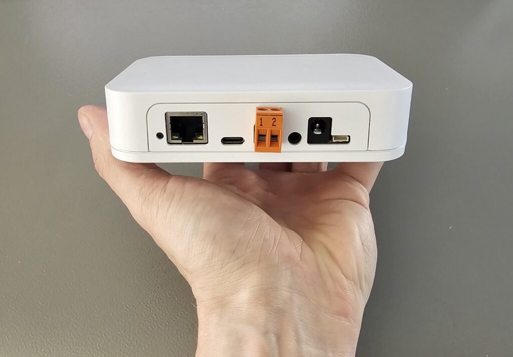
| E32 V2 |  | ESP32 | 16MB | 8MB | *-ESP32-16MB+.bin |
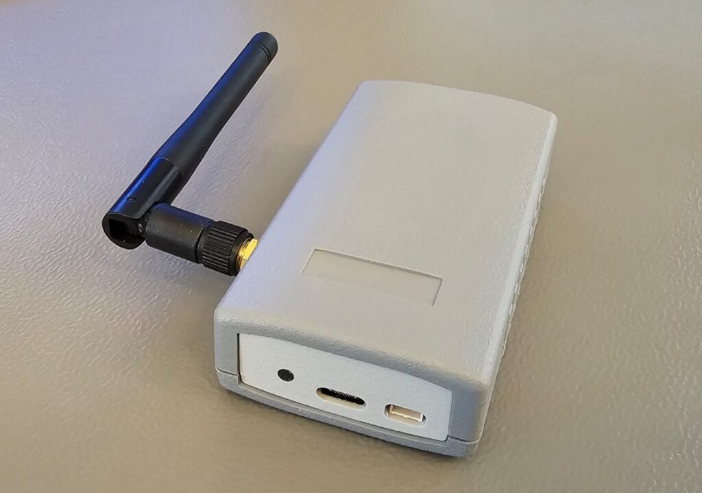
| S3 and S3-LR |  | ESP32-S3 | 16MB | 8MB | -ESP32S3-16MB+.bin |
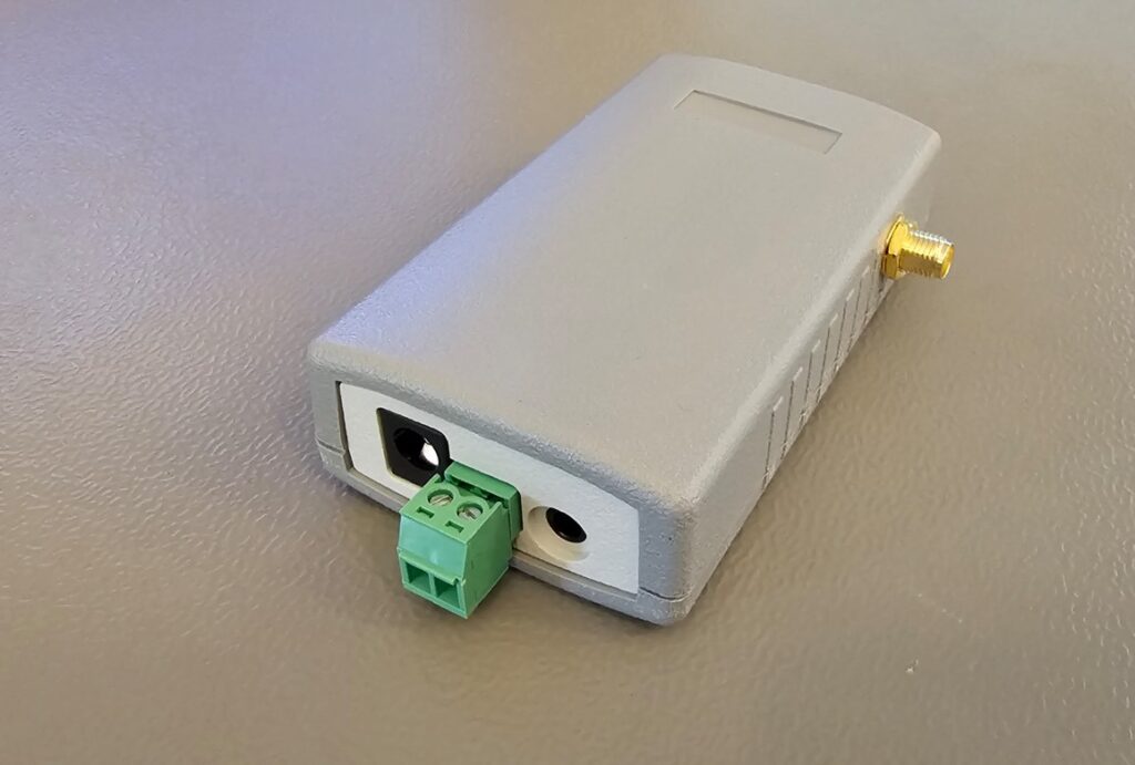
| S32 V2.0 |  | ESP32 | 16MB | none | *-ESP32-16MB.bin |
| S32 V1.1 | 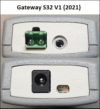 | ESP32 | 4MB | none | *-ESP32-4MB.bin |
| E32 V1.5 | 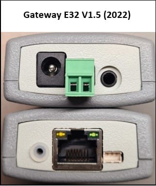 | ESP32 | 4MB | none | *-ESP32-4MB.bin |
| E32 V1.1-V1.4 | 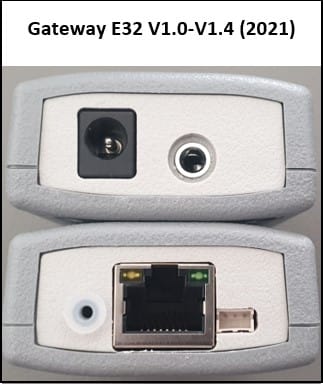 | ESP32 | 4MB | none | *-ESP32-4MB.bin |
If you purchased an EMS interface board, you needed to get your own ESP32 development board. Because there are about 100 different ones available, please check carefully which ESP32 processor it has.
Next check the size of the Flash memory, and then if it has PSRAM.
Currently the most popular board is the Lilygo T7 S3. It has an ESP32-S3 chipset, 16MB of Flash and 8MB of PSRAM. For this one you need the bin file: EMS-ESP-3_7_2-ESP32S3-16MB+.bin.
Another popular cheap board is the MH-ET Live D1 Mini (or clone) module which have the ESP32 chipset, 4MB of Flash and no PSRAM. For this board you need the bin file: EMS-ESP-3_7_2-ESP32-4MB.bin
If you load a bin file without the ‘+’ on the end (meaning it is for boards without PSRAM) onto a ESP module that does have PSRAM on board, EMS-ESP will work. However, the PSRAM is not seen and not activated.
If you load a ‘+’ bin file on a board without PSRAM, it may not boot.