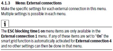
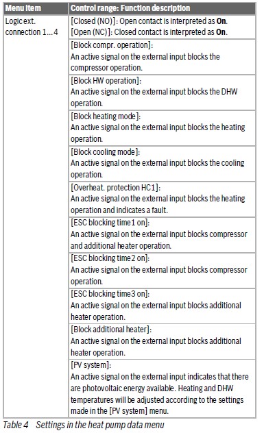
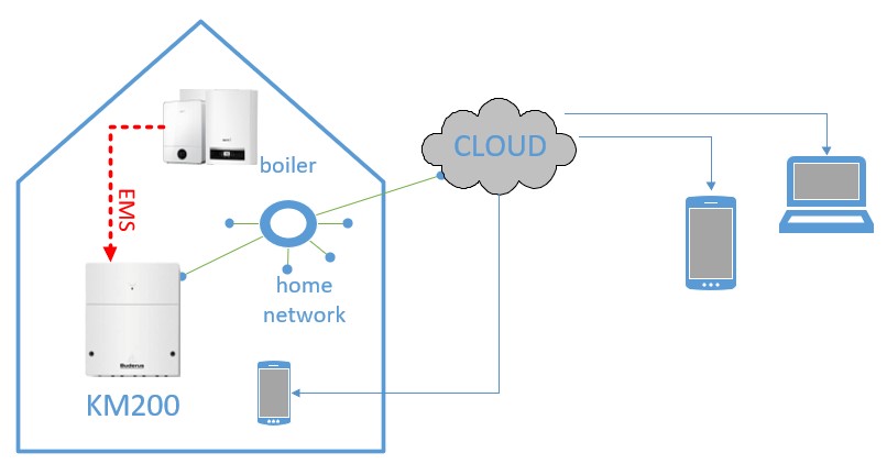
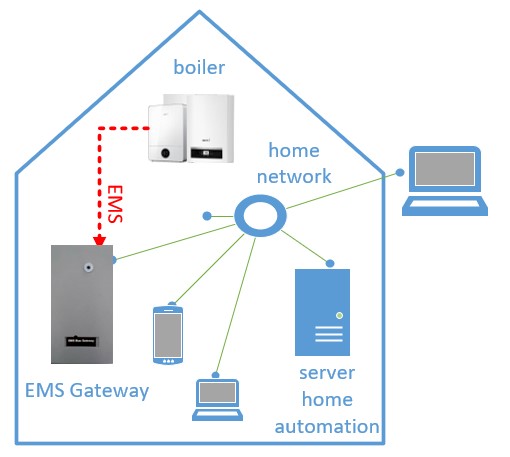
Below various ways to connect the EMS Gateway E32 V2 to the heat source (boiler/heat pump/etc), power and the home network. Also some examples of adding DS18B20 temperature sensors are shown.
There are two ways to connect the EMS Gateway to the EMS bus of the heat source:
- EMS bus accessed via the EMS service jack and the BBQKees EMS service cable
- EMS bus accessed via the EMS screw terminals inside the heat source
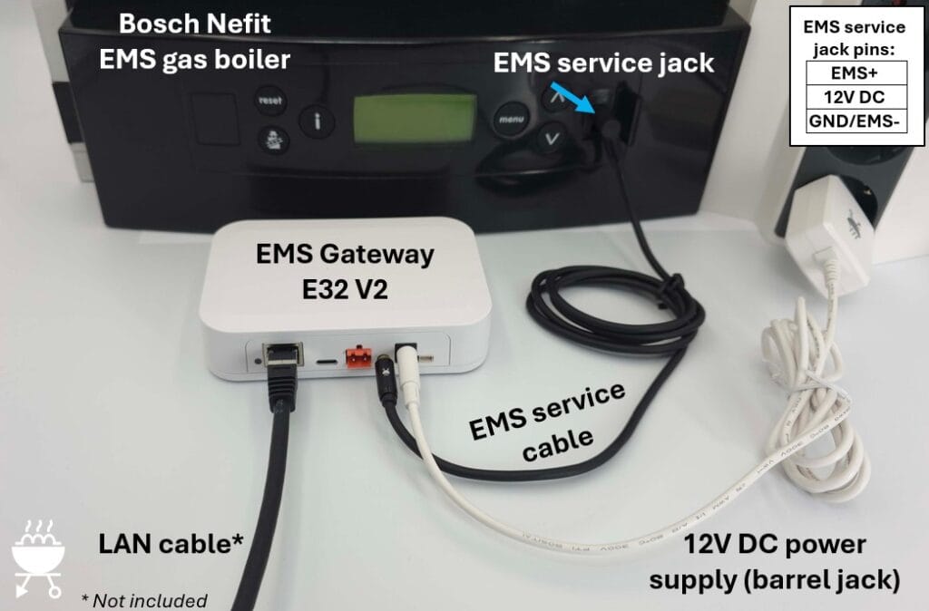
EMS connection via EMS service jack
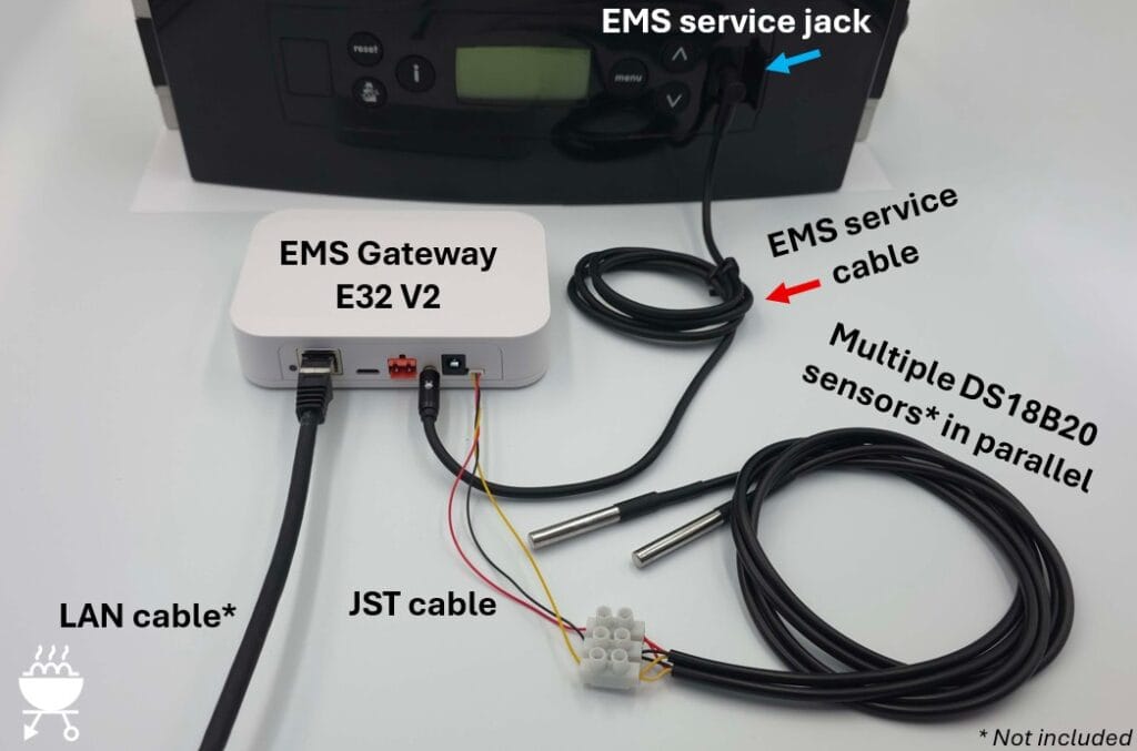
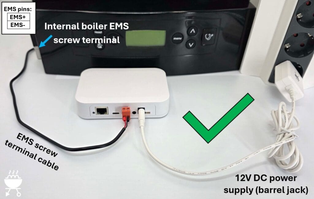
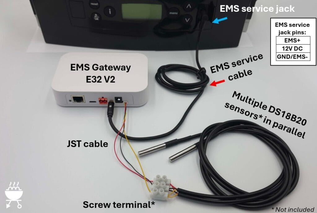
The image below shows the most convenient method to connect the EMS Gateway by using the BBQKees EMS service cable plugged into the EMS Gateway and the EMS service jack of the heat source.
The EMS service jack has both EMS bus wires inside but also a third 12V DC power line for powering the Gateway.
If you use the WiFi feature of the EMS Gateway instead of the LAN port, this single cable is all there is to it!
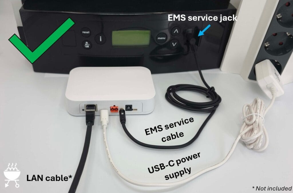
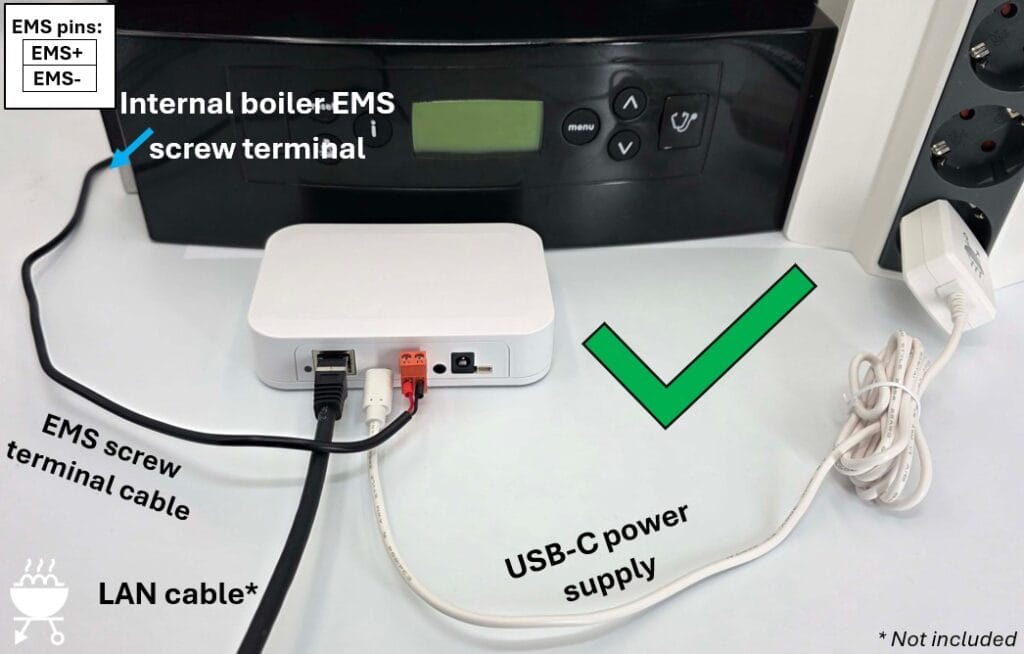
Even though the EMS service jack powers the EMS Gateway, you may want to connect the permanent power supply as well. When the heat source reboots, the 12V DC in the EMS service jack will often momentarily be removed so the Gateway will reboot as well. If this is not preferable you can prevent this by connecting the 12V DC or USB-C power supply to the Gateway as shown below.
Here we also attached a LAN cable, so the EMS Gateway connects to the home network via LAN instead of WiFi.
Depending on when the EMS Gateway has been purchased the product box will have contained either a 12V DC power supply with a barrel jack plug, or a 5V DC USB-C power supply. Just use the type of power supply that came with your EMS Gateway KIT.
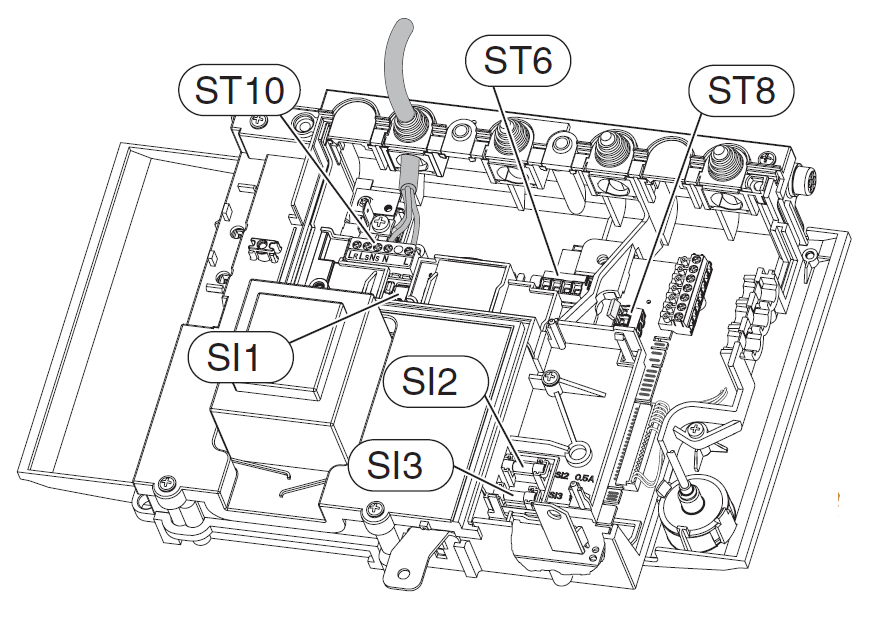
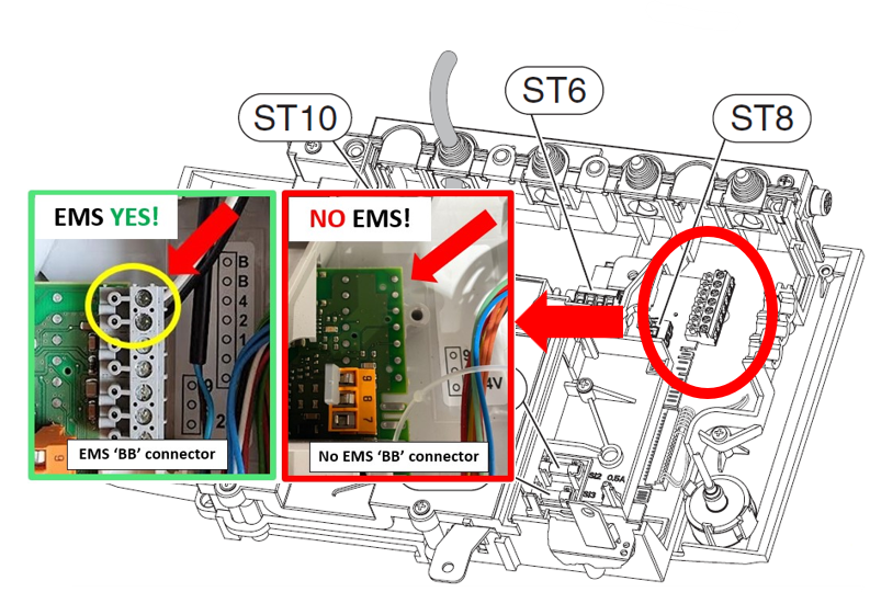
EMS connection via EMS bus screw terminals
When the EMS service jack is not available on your heat source you can connect the EMS Gateway to the EMS screw terminal inside the heat source. Even if your heat source does have an EMS service jack, but you do not want to use it for some reason, you can also use this alternative bus connection method.
Depending on the specific model of boiler or heat pump the EMS bus may be indicated by a number of different icons or markings like ‘BUS’, ‘EMS’, ‘BB’. In general the EMS bus plug is orange on boilers, but usually blue on heat pumps.
Always consult the heat source manual and our extensive product wiki to make sure you are connecting the EMS Gateway to the correct screw terminals. Also turn off the mains power to the heat source before working on it.
If you make use of the EMS screw terminals inside the heat source, you always need to connect an external power supply to the EMS Gateway as well (12V DC in the image below).
This is because the EMS bus cannot power the EMS Gateway over the EMS bus data line.
In the image below the EMS Gateway connects to your home network via WiFi.
In the image below you see the alternative USB-C power supply. The EMS Gateway is connected to the home network via a LAN cable.
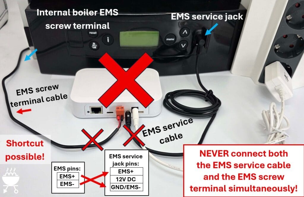
WRONG connection method
The EMS Gateway can be connected to the EMS heat source via the EMS service jack OR the EMS screw terminal. NEVER connect both at the same time. The EMS bus signals EMS+ and EMS- are present in both cables. If you connect both simultaneously, you have a 50% chance of short cutting the EMS bus.
Also NEVER connect the EMS bus of two independent heat sources together.
Adding DS18B20 temperature sensors
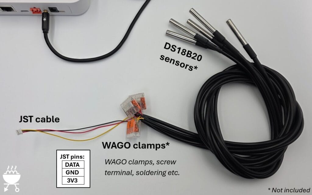
A convenient feature of the EMS Gateways is the possibility to connect (multiple) DS18B20 temperature sensors.
The EMS-ESP firmware automatically recognizes them and will send the temperature information to your home automation as well.
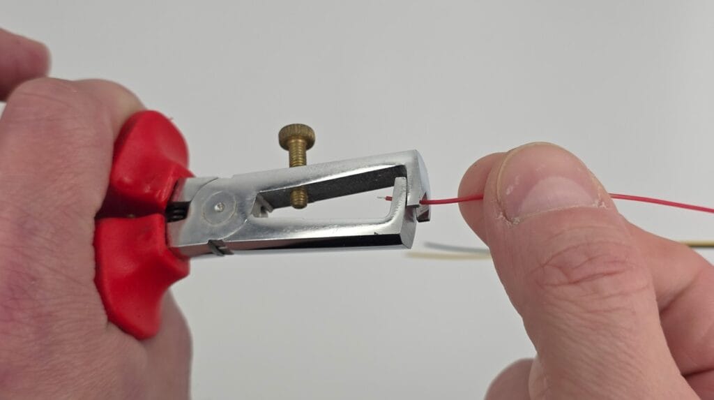
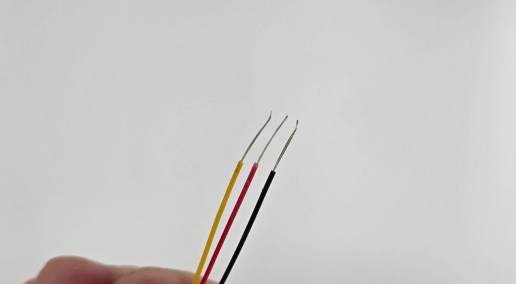
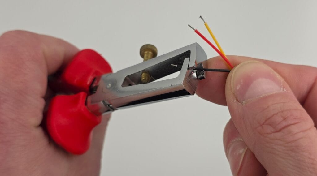
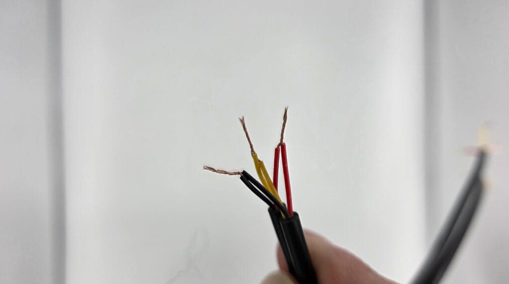
You need to source these DS18B20 sensors yourself. There are several types of these sensors but the most often you will see them in the waterproof version with a cable attached.
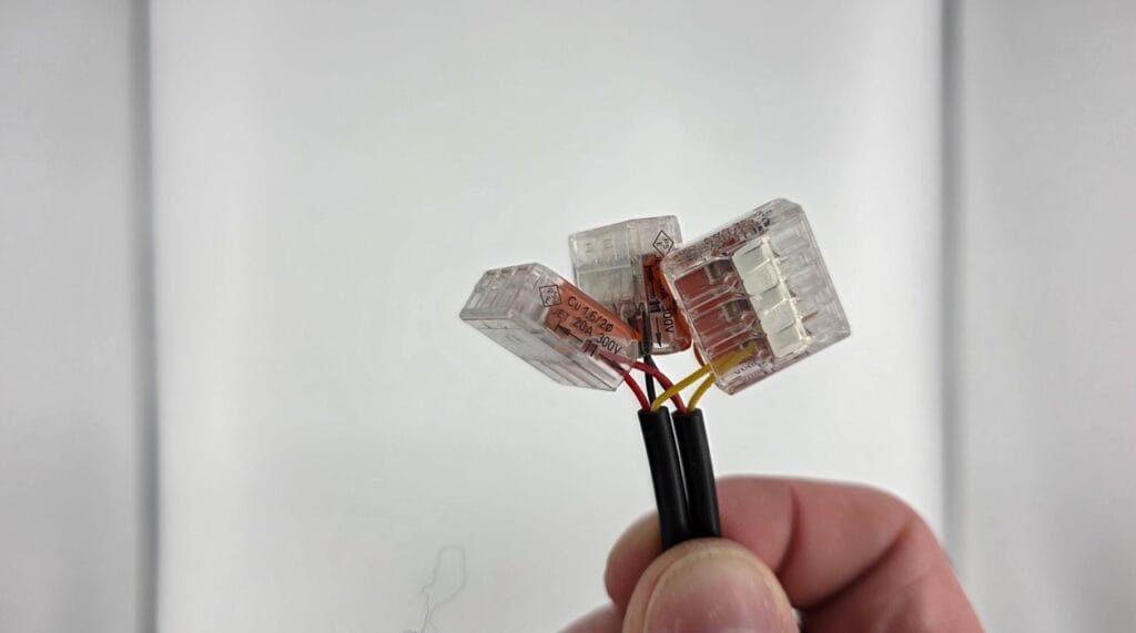
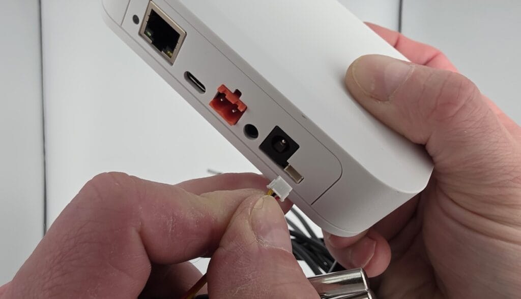
Simply attach one or more of these sensor cables to the small JST cable that is included with each Gateway. Make sure you follow the correct wire colors.
The best way to wire multiple sensors together is by soldering. However, in most cases using a screw terminal or some WAGO clamps will work as well.
When you are sure it is wired up correctly you can insert the JST cable into the EMS Gateway.
In the example below the DS18B20 sensors are wired together with a screw terminal (Lusterklemme). The EMS Gateway is connected to the boiler via the EMS service jack and to the home network via WiFi.
As a final example below a LAN cable is attached so the EMS Gateway connects to the home network via LAN instead of WiFi.