Posted on

Product updates Q3 2025

Product ID fixed

Most products are now getting an internal code ID ‘burned’ into the memory of the ESP32 chip during production to identify the product and the batch number of its’ circuit board.
The latest EMS-ESP development firmware 3.7.3 version 15 or higher will detect this ID and fix the board profile accordingly.
Firmware 3.7.3 is not a stable release yet, but as the latest stable 3.7.2 does not have the internal code to look for this ID, all production boards which contain a product ID are loaded with the 3.7.3 dev15 or higher firmware.

In the past, a faulty firmware update could for instance reset the board profile to the default S32, which would render the Ethernet port inoperable. You would then have to log in via WiFi, set the board profile back to E32 V2 and reboot to get the Ethernet port working.
With the product ID fixed inside the ESP32, the firmware will then automatically recover and use the correct board profile.
If you are a developer who likes to play with custom board profiles on a BBQKees Gateway product, you need to take into account that the default EMS-ESP firmware will keep setting the board profile according to the product ID found.

The product ID is burned into the ESP32 chip, so this is persistent over firmware updates and will even survive a full erase of the flash memory.

How can I check if a product ID has been set?

If you visit the Hardware tab on the Status page of the web interface, the ‘Hardware device’ will show the BBQKees logo and will tell you which board revision and batch number it is.
If it does not show the BBQKees logo and give just the ESP32 chip revision, it will not have the product ID fixed.

Alternatively, you can use the terminal to check. Open a terminal on the Gateway via Telnet or serial en type in ‘show’.

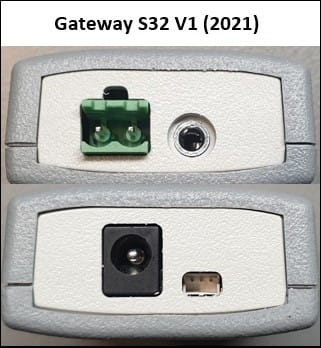
If there is no fixed product ID, the model description will be empty. If a product ID was found, it will show the specification. Below on the left a board with product ID and on the right a board without product ID.

What happens when I load new firmware on a BBQKees product without a product ID?

Nothing will happen to the board settings when you update the firmware on an existing BBQKees product without fixed product ID. So it is backwards compatible.
However, if the product ID is set, any firmware from 3.7.3 dev15 and onward will fix the board profile to the one belonging to the product ID. So custom board profiles may be overruled.
If you use a custom board profile on a genuine BBQKees board you are probably a developer yourself so you will know how to change the board profile back to a custom one.

Discontinuation of the EMS Gateway S3

The manufacturer of the grey enclosure of the S3 and S3-LR Gateways has stopped production entirely earlier this year. We purchased all remaining stock we could find but our S3 enclosure inventory is almost depleted now.

Because of this, we were forced to revisit our product portfolio.
The S3 and E32 V2 Gateway models have only slight differences aside from the absence of LAN/Ethernet on the S3. As the more feature-rich Gateway E32 V2 is already our existing main product, we basically have an S3 ‘successor’ at hand.
Designing an completely new S3-like product in a new enclosure from scratch is a huge amount of work. It’s not just selecting an enclosure and fitting the circuit board to this new box, but you need to go through all the regulatory and compliance testing again which is both a pain in the ass and expensive. And after that create new manuals, instructions, design new packaging, incur new GTIN/EAN fees, etc etc.
Therefore we decided to focus solely on the E32 V2 instead of creating an additional successor of the S3.

Over the past 2 years we had plenty of time to refine the existing E32 V2, which will be able to handle all the stuff we can think of in the coming years thanks to its big and future proof 16MB Flash and 8MB PSRAM memory.

Time frame remaining stock

We will discontinue the S3 product line after the current stock has sold. We expect to sell out within a number of weeks or by the end of Q3 2025 at the latest. So if you like to get your hands on a small WiFi-only EMS Gateway you have to decide soon!
There will not be a sale on the remaining S3 or S3 KIT products. Business customers who would to get some S3 before it sells out, just send us an email for a quote.

The previously available S3-LR will not get into new production anymore obviously (we had a number of people on a waiting list).

Warranty and parts availability

The S3 Gateway will still be supported in future EMS-ESP firmware releases and you still get the 2-year BBQKees warranty. We are committed to long term service and are thus keeping an inventory of spare boards and other S3 parts for warranty replacements.

Posted on

Holiday time June 2025: limited product selection and limited shipping

Due to multiple overlapping holidays of our staff we will offer a limited selection of products in the period from Friday 6 June until Monday 23 June. Also shipping for some countries (non-EU) will be delayed until Tuesday 24 June.

Product availability

We will only sell the EMS Gateway KIT products and the EMS service port adapter plug accessory.
The specific products available for sale and immediate shipping are:

There is a large stock available of the products above.
As long as any of the above products are in stock, you can put them into your shopping cart and purchase them right away. They will be shipped in the same week (for EU countries).

All other products in our store can be purchased again starting Tuesday 24 June.

Limited shipping for some countries

DPD normally picks up the packages three times a week (Monday, Wednesday and Friday). This will be limited to two times a week (Tuesday and Friday). In general this means you have to add one day to the delivery of your package.
Orders placed between Friday 6 June until Monday 23 June are shipped within the same week only for destinations in the following EU countries:

  • Germany
  • the Netherlands
  • Belgium
  • Luxembourg
  • Austria
  • Poland
  • Denmark
  • Sweden
  • France
  • Latvia
  • Slovenia
  • Slovakia
  • Czech Republic
  • Hungary

Customers from other EU countries and all non-EU countries can still purchase the 3 available products in this time period, however shipping will be delayed until 24 June.
This has to do with non-EU countries needing export documents and countries to which DPD does not ship If you order a product from any other country not on the list above, the ordered products will be reserved for you but the shipment will be deferred to 24 June.

These countries include:

  • UK
  • Switzerland
  • Norway

So if you order a KIT product from Germany on Monday 16 June it will be shipped Tuesday 17 June.
If you order the same KIT product from Switzerland on Monday 16 June it will be shipped Wednesday 25 June.

End of ‘holiday-mode’

Starting from 24 June operations will resume as normal again. This means the full product catalogue will be available again and shipping to all countries will resume as normal.

Posted on

Choosing the correct firmware bin file for your BBQKees product

When you want to update via USB or you need to load a specific firmware version on your BBQKees Gateway, you have to upload the correct bin file to your Gateway or otherwise you may brick it.

For uploading a new firmware to your Gateway via USB you need to use the EMS-ESP flash tool. See the wiki here for more instructions. In some cases you can manually download the firmware, and upload it via the web interface of the Gateway.

On the EMS-ESP Github repository you can download the firmware bin files. The naming convention since firmware 3.6.5 is structured according to the chip type (chipset) and features, and does not have the name of a Gateway product in it.

It is structured like below:

EMS-ESP-<version>-<chipset>-<flashsize>[+].bin

where <chipset> is ESP32 or ESP32S3 and <flashsize> either 4MB or 16MB. The + indicates that the firmware is built to use any additional RAM (called PSRAM) if available.


See the EMS-ESP download info page here for more information.

If you want to upload a specific firmware version 3.7.2 to lets say a new E32 V2 Gateway, you first need to lookup which ESP32 chip is used. The E32 V2 has a ESP32 chipset with 16MB of Flash and 8MB of PSRAM. The filename of the bin file would then be EMS-ESP-3_7_2-ESP32-16MB+.bin.

Below a handy list about which Gateway model has which features and thus needs which firmware bin file.

So firmware version 3.7.2 for the EMS Gateway E32 V2 is this one:
https://github.com/emsesp/EMS-ESP32/releases/download/v3.7.2/EMS-ESP-3_7_2-ESP32-16MB+.bin

As a second example say you would like to get the 3.7.1 firmware for the S3 Gateway.
That’s the following bin file:
https://github.com/emsesp/EMS-ESP32/releases/download/v3.7.1/EMS-ESP-3_7_2-ESP32S3-16MB+.bin

ModelSide imageESP32 chip typeFlash storagePSRAM storageFirmware name ends with
E32 V2ESP3216MB8MB*-ESP32-16MB+.bin
S3 and S3-LRESP32-S316MB8MB-ESP32S3-16MB+.bin
S32 V2.0ESP3216MBnone*-ESP32-16MB.bin
S32 V1.1ESP324MBnone*-ESP32-4MB.bin
E32 V1.5ESP324MBnone
*-ESP32-4MB.bin
E32 V1.1-V1.4ESP324MBnone*-ESP32-4MB.bin

If you purchased an EMS interface board, you needed to get your own ESP32 development board. Because there are about 100 different ones available, please check carefully which ESP32 processor it has.
Next check the size of the Flash memory, and then if it has PSRAM.

Currently the most popular board is the Lilygo T7 S3. It has an ESP32-S3 chipset, 16MB of Flash and 8MB of PSRAM. For this one you need the bin file: EMS-ESP-3_7_2-ESP32S3-16MB+.bin.
Another popular cheap board is the MH-ET Live D1 Mini (or clone) module which have the ESP32 chipset, 4MB of Flash and no PSRAM. For this board you need the bin file: EMS-ESP-3_7_2-ESP32-4MB.bin

If you load a bin file without the ‘+’ on the end (meaning it is for boards without PSRAM) onto a ESP module that does have PSRAM on board, EMS-ESP will work. However, the PSRAM is not seen and not activated.

If you load a ‘+’ bin file on a board without PSRAM, it may not boot.

Posted on

New product packaging for KIT products

It took more effort than expected but finally we have a dedicated product packaging for the E32 V2 / S3 EU KIT products.

It’s a strong cardboard box made from recycled materials. The interior of the box is made from the same plain eco-cardboard material. It fits though the mail slot.

In the coming weeks the old plain packaging will be slowly replaced by this new branded product packaging for the EU KIT versions. Unfortunately the UK plug by design is too big to fit through a mail slot and therefore the UK KIT packaging needs to be bigger. These will continue to be sent in generic cardboard packaging.

BBQKees.com new product packaging

The E32 V2 Gateway sits on the left and the power supply and bag with cables and accessories sit on the right.

E32 V2 KIT product packaging

And the same interior piece also fits the S3 Gateway so we have only one interior for both products.

Posted on

Adding DS18B20 temperature sensors to your Gateway (without soldering)

This guide will show you how to easily add some DS18B20 temperature sensors to your BBQKees EMS Gateway.
No soldering skills necessary.

You can add DS18B20 sensors to all BBQKees Gateways ever made by using the small 3-wire JST cable that is supplied with each Gateway order.

The easiest to use are waterproof DS18B20 sensors with a cable. These are cheap and convenient to use.
We do not sell these sensors, they are available at many places online.


You can add a number of these sensors in parallel to a Gateway. The specific number varies depending on the length of the cable and the type of DS18B20 sensor used. But in general 10 sensors is usually not a problem.

Make sure the sensors are all of the same DS18B20 sub-type and do not mix parasitic mode with normal mode wiring.

Prerequisites and parts

  • BBQKees EMS Gateway
  • 3-wire JST ZH cable
  • DS18B20 waterproof sensors with cable
  • 3 Wago 221 splicing connector with levers or f.i. a ‘lusterklemme’
  • Wire stripper
Parts for adding DS18B20 sensors

Step 1: Strip the wires on the JST cable

You need to strip the wires on the JST cable by about 10mm. If the wire ends are soldered, it’s better to cut them off at the point of the wire insulation before stripping. This will make stripping the wires easier.

Stripping JST cable
Stripped JST cable

Step 2: Strip the wires on the DS18B20 sensors

Strip them 10mm, or at least the same length as you stripped the JST cable.

Step 3: Tie the wire ends together

Tie the wire ends together. Tie each color separately. So all yellow wires together, all black wires together and all red wires together.
If there are too many cables, you can also do 2 or 3 cables each time.

Tied cables

Step 4: Put each wire color in a separate Wago clamp

This step is where you could make the most errors so be careful here.

You need to insert each cable bundle of it’s own color into a separate Wago clamp.
DO NOT put any other wire color in the same clamp as this will cause shortcuts.

Wire ends in Wago clamps
End result DS18B20 sensors in Wago clamps

Step 5: Insert the JST plug into the EMS Gateway

Insert the JST plug into the JST connector in the Gateway. You need to keep the flat part of the plug at the top. Make sure it is fully inserted. See the image below for the correct orientation.

It’s best to turn off the Gateway before doing this. If the Gateway does not boot afterwards, you made a shortcut in the wiring.

Inserting the JST cable

Step 6: Check the EMS-ESP web interface and rename the sensors

If everything went correct, you will see the sensors appearing in the Sensors tab in the web interface.

Sensors tab EMS-ESP web interface

Each DS18B20 sensor has it’s own unique address identifier. These identifiers are displayed.
You can click on one to rename it.
After you rename a sensor, it is also renamed in MQTT and Home Assistant etc.

Renaming sensors

If you added a bunch of sensors at the same time, it can be hard to distinguish them.
You can heat each sensor separately with f.i. a hair dryer or heat gun and see which one gets hotter.

And that’s it!

Posted on

Updated guide on integrating an EMS Gateway into your Home Assistant

I have updated the guide on how to connect an EMS gateway into Home Assistant.
The old guide was a bit outdated, and as most EMS Gateway customers use Home Assistant as their Home automation, up to date guides are necessary.

Logo wordmark Home Assistant

It uses a fresh install of Home Assistant version 2025.2.1 installed as HA OS on a Raspberry Pi as a starting point. So only the initial Home Assistant setup has been done. Creating a HA user and that’s it before we configure anything else.

Steps

In short these are the steps you need to take to get all the EMS entities into Home Assistant in a few minutes:

  • Log into Home Assistant
  • Create a new user in Home Assistant for MQTT
  • Install the MQTT integration in Home Assistant
  • Connect the EMS Gateway to the bus and log into the web interface
  • Configure the MQTT settings in the Gateway
  • BOOM! all entities will show up in Home Assistant within a few minutes.

See the following link to the wiki: https://bbqkees-electronics.nl/wiki/home-automations/home-assistant-configuration.html

Posted on

28 October 2024: Firmware 3.7.0 release now available

After 6 months and 47 beta versions EMS-ESP32 firmware 3.7.0 has finally been released. It packs hundreds of improvements, new features and bug fixes.

Updating to 3.7.0 from 3.7.0dev

If you were already on a development version of 3.7.0, you can update the firmware via the update feature of the web interface.

Updating from 3.6.4 or 3.6.5 to 3.7.0

If you are currently on 3.6.4 or 3.6.5, you cannot update via the web interface directly.

Clicking on the bin file will result in an error. This is because after 3.6.5 the firmware bin file naming scheme has changed, so the 3.6.5 firmware is looking for a bin file on the Github repository that does not exist.

In this case go to the releases page of the firmware repository and download the correct bin file.

You can use the table here for getting the right file.

After you have downloaded this file to your computer, you can upload it via the EMS-ESP web interface.

After the reboot of the Gateway, press F5 to clear the browser cache otherwise there may still be some left overs of the old interface in the cache, causing strange UI combinations of both the old and the new user interface.

Possible issue with updating to 3.7.0 with the E32 V2

In some cases after the new firmware upload, the Ethernet interface of the E32 V2 may be disabled. Don’t worry, it’s not dead. In these cases the board profile of the firmware has accidentally defaulted to the S32 Gateway, which has no Ethernet.

To correct this, log in to the ems-esp WiFi network, go to settings and change the board profile to E32 V2. Then save and reboot and Ethernet will become alive again.

Posted on

Using the Smart Grid (SG) and Photovoltaic (PV) function of your heat pump with the EMS Gateways

Input 4 options

Almost every Bosch/Buderus/Nefit heat pump with an EMS bus has 4 external inputs. These can be used to block the operation of the pump etc, but also for Smart Grid (SG) and Photo Voltaic (PV) features. You can virtually switch these inputs with all EMS Gateways to have the heat pump operate in a specific way.

Currently it’s a bit of a read and some trial and error but once set it will work automatically.

(There is also similar information in the EMS-ESP documentation.)

Every Bosch heat pump has 4 of these inputs, it depends on the country and your specific system but usually input 3 and/or 4 can be used for SG and PV.

You need to check the system menu or the installation manual of the heat pump to check which features are supported on which input. In the installation manual you can see which action the heat pump can do when one of these inputs is enabled. If you cannot find the information in the installation manual, you need to look up the manual for the controller/display of your unit (Likely the UI800 or HPC410).

The section you need to look up is called “Menu: External connections” and will look something like below.

If you look into the following example of the installation manual of the Compress 6800i, then PV and SG are both on the input 4.

Heat pump External connections menu settings
Heat pump external connection feature table

This menu will list all configurations that are possible to set for each input.
The Smart Grid and PV System menu are the most interesting.

Smart Grid settings Bosch heat pump
PV menu setting Bosch heat pump

In the web interface of the Gateway you can see the input state of each input, and also the configuration of each input. In the example below the options for input 4.

Input 4 state
Input 4 options

If you change the configuration the the menu to the SG and/or PV feature you want to activate, you can see the corresponding input values.

You can send these same values from Home Assistant to the Gateway to enable these features.

However, the heat pump expects the actual input to be enabled. But there is nothing physically attached to the inputs. But there is a workaround. The first bit of the configuration will tell the heat pump if the signal is active high, or active low.
So it should enable the function if the physical state of the input is ‘Normally Open’ and thus enabled when closed, or ‘Normally Closed’, and thus enabled when open. What we need is the second one. As the manual describes: “Open contact is interpreted as ‘ON’“.

If we invert the logic here, and attach and detach the configuration to the input every time we need it, you can turn on or off the PV and SG feature of your heat pump with your EMS Gateway.

You can use the same logic to activate the ‘EVU Sperre’ feature etc.

Posted on

Accessing the EMS/BB terminal on a Junkers or Worcester boiler (and some Bosch as well).

To connect an EMS Gateway to a Heatronic 3 boiler like most Junkers, Worcester and some Bosch boilers you need to gain access to the EMS/BB screw terminal inside the boiler.

The guide is for all boilers that look like this:

General fascia appearance of a Heatronic 3 style boiler

Step one: disconnect the boiler from power

A good first step is to unplug the boiler from mains power for safety.

Step two: unscrew and unhinge the front cover

There are small variations between these models but in general they are held by 4 screws. Two are located at the bottom near the front. One on the left and one on the right.

On the top of the boiler there are usually also two screws, although some covers are held by a clip.

You can unscrew all screws that are holding the metal front cover. Don’t worry it won’t fall off because it is still held by clamping.

Next you need to pull the underside forward and then slightly up and the whole cover will come off pretty easily. It only weighs a few kilo so it’s a simple one-person operation.
If it does not come off easily, there may still be a hidden screw somewhere so don’t use force and see if you missed a screw somewhere.

Step three: flip down the control panel

Flipping down the control panel on a Heatronic 3 boiler

The control panel is held by a single screw on the top (nr. 1). Unscrew it and then you can flip down the control board.

Step four: Remove the connection cover

Removing the connection cover on a Heatronic 3 boiler

The connection cover is held by three screws. Unscrew them (nr. 1) and remove the cover.

Step five: Accessing the screw terminals on the control board

Now that the cover is off, you can access the EMS screw terminal marked ‘BB’ on the control board.

The control board of a Heatronic 3 boiler

As mentioned above the EMS bus data lines are located on ST19 on the ‘BB’ terminal pins.

Finding the BB Screw terminal block on a Heatronic 3 control board

See if there is a grey screw terminal block mounted as above. If not, there is no EMS bus on your boiler. If there is a terminal block, please check if there is about 15V DC between the BB pins. If so, you can go ahead and attach an EMS Gateway to these pins. If there is nothing or only a few mV present, there is no EMS bus active on this port. You can look for it on another part of the circuit board. On Junkers boilers there is always an EMS bus present on the BB terminal.

For Worcester availability of the EMS bus on the BB pins depends on the specific boiler model and whether an integral diverter valve kit has been installed or not. For some boilers that don’t have an active EMS bus it’s possible to swap out the code plug so it becomes active.

If you do not have an active EMS bus on the BB pins it may still be active on the other side of the circuit board. See the image below. Also see the wiki HERE.

Alternative EMS bus location on Worcester circuit board
Posted on

Powering the E32 V2 EMS Gateway via passive POE

Sometimes there is no easy way to make a 230V wall outlet or power socket near the boiler or heat pump. The E32 V2 has Ethernet, but is does not support active POE (Power Over Ethernet), which is usually 48V or 24V.

What you can do instead is use a so called ‘passive POE cable kit’ like the Digitus DN-95001 to inject the 12V DC of the BBQKees Electronics power supply to the E32 V2 over the same Ethernet cable as the LAN signal.

Each Ethernet cable has 8 leads, 4 of which are used for data and the other 4 are used for power.

These cable kits will also work for longer distances of Ethernet cable where the 12V voltage may drop a bit, because the E32 V2 will still work with f.i. 9V DC. And the bitrate of the connection is relatively low at just 100Mbit.

Below an image of such a cable kit. The female Ethernet connectors are for connecting to the Ethernet cable from the router location to the Gateway location. And then one side has a Ethernet plug which you plug into your router or switch and a female receptacle for the 5,5mm DC barrel jack plug of the 12V DC power supply.
The other cable in the kit has a male Ethernet plug and a 5,5mm male barrel jack plug for connecting to the Gateway.

Below an example setup. On the left you connect the combiner cable to your router or switch, and you plug in the 12V DC power supply to the connector on that cable.
On the receiving end you connect the incoming Ethernet cable to the splitter cable, and then the Ethernet plug of the splitter cable and the barrel jack plug into the E32 V2.

Please pay attention if your switch or router has 24V or 48V POE enabled on that specific port and you are using this passive cable set at the same time, you may blow up the Gateway. Of course I do not give any warranty if you fry the circuit board. Furthermore this page is just for reference. Always know what you are doing when messing with voltages and cables. The above example may or may not work in your specific situation.