How to connect the board
Available connectors
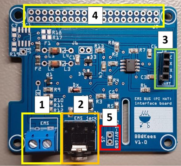
Available connectors on the V1.0 board
Number |
J# |
Function |
Remark |
|---|---|---|---|
1 |
J1 |
EMS screw terminal |
Polarity does not matter. |
2 |
J3 |
EMS service jack plug |
Only connect either J1 or J3. |
3 |
J2 |
Controller UART header |
VCC/TX/RX/GND. Input 5V or 3.3V from controller. |
4 |
J7 |
Raspberry Pi header |
40-pin header for the Raspberry PI. |
5 |
J5 |
8~16V pin from EMS service jack |
Left pin EMS 8~16V DC. Right pin GND. Max power draw 200mA cont. |
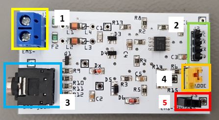
Available connectors on the V0.9 board
Number |
J# |
Function |
Remark |
|---|---|---|---|
1 |
J1 |
EMS screw terminal |
Polarity does not matter. |
2 |
J2 |
Controller UART header |
VCC/TX/RX/GND. Input 5V or 3.3V from controller. |
3 |
J3 |
EMS service jack plug |
Only connect either J1 or J3. |
4 |
J4 |
RX resistor selector |
Select either 4k7 or 100E resistor. |
5 |
J5 |
8~16V pin from EMS service jack |
Left pin EMS 8~16V DC. Right pin GND. Max power draw 200mA cont. |
Connecting to the controller
The controller needs to power the interface board. Connect GND as well. Do not supply the interface board with more than 5V.
You can connect this board to any 5V or 3.3V compatible UART. This might be on an Arduino, ESP8266 or f.i. a Raspberry Pi. Connect the header J2 to the controller. For the V0.9 board use the jumper of J4 to select the correct RX UART resistor setting. For most Arduino’s and the Pi this is setting 1. This setting provides a standard 4k7 Ohm resistor on the output. For the ESP8266 use setting 2. Setting 2 provides a 100 Ohm resistor on the output, specifically intended for the ESP8266 and other similar chips. If one particular setting does not work, try the other setting too. Connect RX to the RX UART serial port and TX to the TX UART serial port of your controller. If you do not need TX you can just leave the pin unconnected.
Warning: If you are using the Raspberry Pi header on the V1.0 board do not connect any 5V to the UART header!
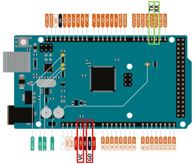
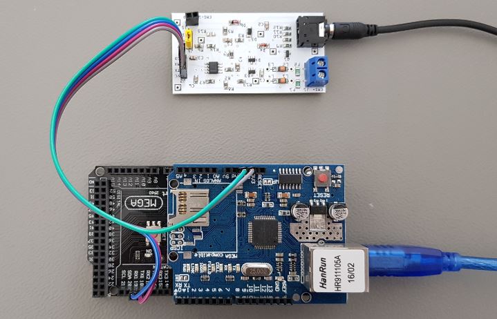
Arduino
On the Arduino Mega 2560 in combination with the Github sketch connect RX to RX1 (pin 19) and TX to TX1 (pin 18). Connect VC to 5V and GD to GND. If you use an Arduino UNO you have no choice other than RX on pin 0 and TX on pin 1. In case you use the UNO do not connect the EMS board to the Arduino while you are programming the Arduino, because the same serial pins are used for programming the Arduino.
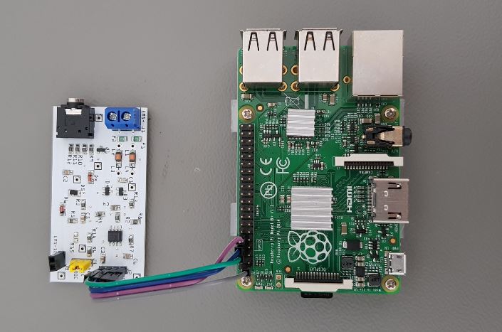
Raspberry Pi
On the Raspberry Pi connect RX to GPIO 15 (pin 10) and TX to GPIO 14 (pin 8). Connect VC to 3V3 on pin 1 of the raspberry Pi header.
Warning: If you are using the Raspberry Pi header on the V1.0 board do not connect any 5V to the UART header!

Wemos D1 Mini

Pin on EMS board |
Pin on Wemos |
|---|---|
VC |
3V3 (NOT 5V!) |
TX |
D8 |
RX |
D7 |
GD |
G or GND |
Power the EMS board with 3.3V from the Wemos. Do not use the 5V pin as this will damage the I/O pins of the Wemos. The normal TX and RX pins on the Wemos are marked TX and RX, however for EMS-ESP this is set do D7 and D8. This is because the Wemos at boot sends debug information on TX and this disrupts the EMS bus.
Drawing power from the service jack
The interface board also puts out the 8-16V pin of the EMS service jack via header 5. This can be used to power small electronics. (There will only be power on this pin if you use the service jack, the screw terminal does not have the third pin). If you do draw power from the EMS service jack make sure the 3.5mm jack cable you use can handle the current as most of these cables are meant for audio and therefore have very thin wires inside. The best method to power external circuits from these pins is to use a buck converter. LDO’s will overheat pretty quickly due to the voltage difference. Also take care you do not short circuit the board in any way or feed this board with incorrect voltages as this may damage the board or the EMS bus. Also make sure the wires you connect the board to are in fact EMS bus wires and NOT 24V or mains power lines!!!!!!!!!
Drawing power from the EMS bus
The interface boards are not designed to draw power from the EMS bus. So you cannot power your microcontroller via the bus. Because of the way TX data transmissions work on the EMS bus, the circuit must be finetuned to a specific current draw of the electronics on the bus, otherwise it will not work. As the interface boards can be used with any microcontroller, they are designed so they can be safely used by all microcontrollers and are thus not tuned to a specific current.
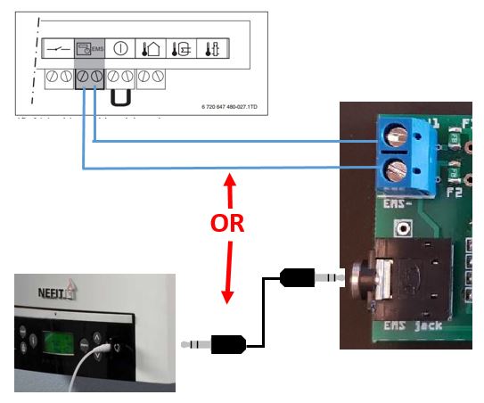
Connecting to the EMS bus
You can use EITHER the EMS bus service jack OR the screw terminal. Do not connect them at the same time, because you might short circuit the bus. If you use the screw terminal, polarity does not matter because the circuit bord corrects both orientations.