Connecting the Gateway to the boiler side
You can connect the Gateway to either the service jack of the boiler or heatpump (if it has one) or you can connect it to the EMS bus wires on the side of the boiler or the side of the thermostat or module.
Service jack
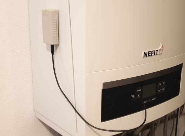
With the supplied jack cable you can plug in the Gateway to the service jack of the boiler. This is usually located on the front of the boiler below a rubber or plastic flap. (The service jack for heat pumps is often hidden away as a seperate cable inside the housing.) The entire device is powered via this service jack. So no additional power supply needed. Just the jack cable is all you need.
Switch off the boiler or heat pump. First plug in the cable to the Gateway and then into the boiler or heat pump. Press the plug firmly in the connector or both sides. Turn on the boiler or heat pump. If the Gateway is plugged in correctly, it will start blinking slowly to indicate it’s working and looking for the EMS bus and WiFi network.
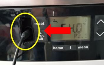
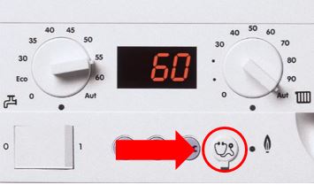
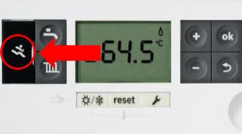
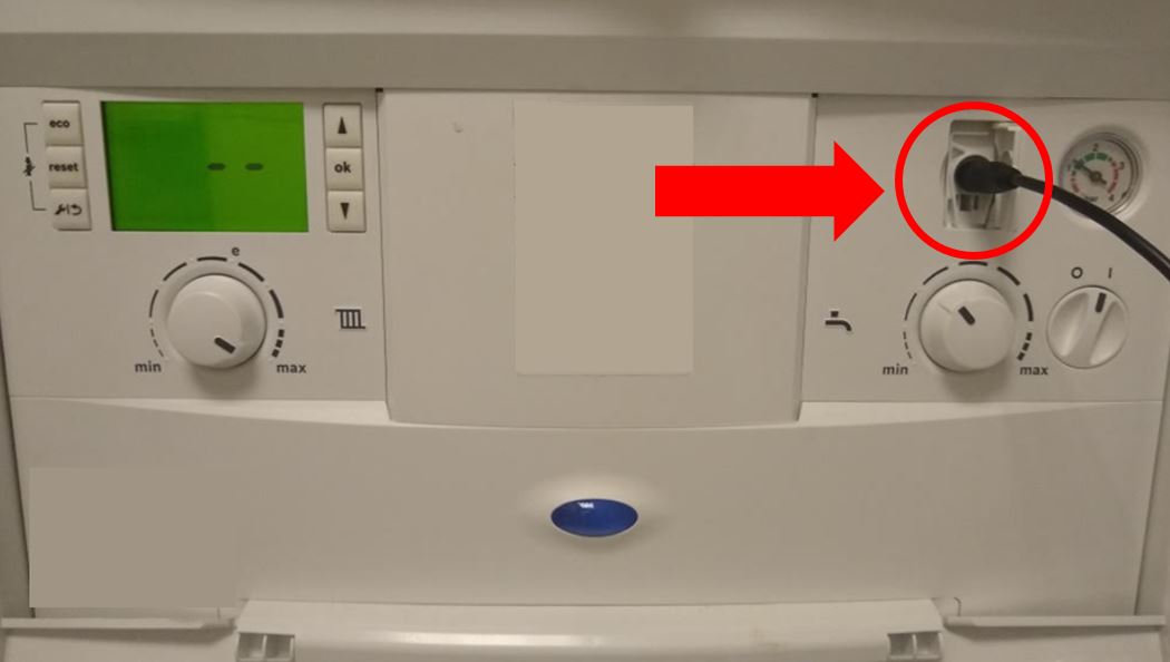
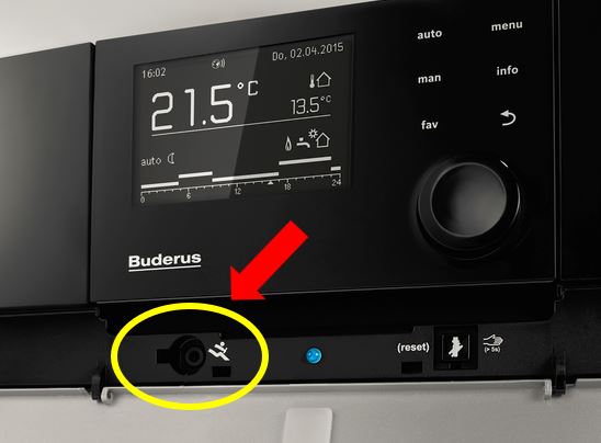
Below some examples of service jack locations.
Service jack on boilers
There are more possible locations, but not all boilers have a service jack. In general ALL Nefit boilers, most Buderus and Bosch boilers, and some Junkers boilers have a service jack.
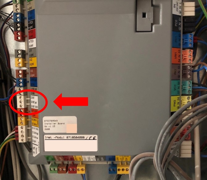
Service jack on heat pumps
Almosty all heat pumps have the service jack as a cable inside the housing (You can also stick the whole Gateway inside):


The cable starts from the white BBT connector on the side of the grey installer board.
EMS/thermostat wires
If your boiler does not have a service jack or it does but you want to mount the EMS Bus Gateway elsewhere you can use the screw terminal to connect to the two EMS bus wires. This can be in parallel with the thermostat or from inside the boiler.
Note
You can connect the Gateway near the thermostat but it will perform better if you connect it near the boiler.
Inside the boiler there is a row of electrical screw terminals which will resemble something like the examples below. There might be a short row of terminals but for some boilers there might be 20 terminals or more.
Danger
Be careful when accessing the inside of the boiler. Mains voltage is present. Unplug the boiler from the mains voltage before continuing.
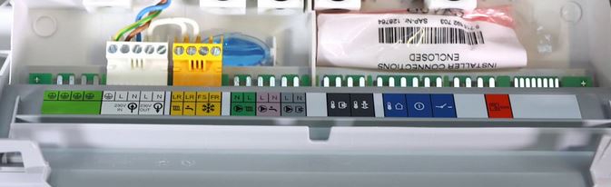
Now you need to find the EMS bus terminal connector. Usually this connector is orange or white for boilers and modules and blue for heatpumps. If your boiler has an EMS thermostat connected, it will also be connected to this terminal. For some Junkers boilers the terminals are green and marked ‘B’ and ‘B’, or ‘RC’.
Below a number of possible EMS bus connector types from several boiler models.
On the next page there is also a more detailed guide with examples on many specific boilers and heatpumps. See: Connecting the Gateway to specific boilers and heatpumps.
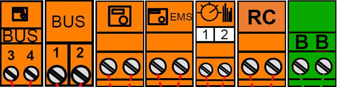
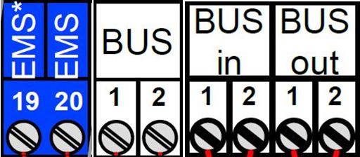
If your boiler has multiple EMS bus connectors, connect the Gateway to the orange/blue one or to a connector which is already wired to an EMS bus device. If your EMS module has both an EMS IN and EMS OUT connector, first try out EMS OUT and if that does not work use the EMS IN. If your EMS module has multiple numbered EMS bus connectors, connect the Gateway to the EMS bus connector that is orange or to the connector that has no number.
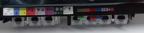
Warning
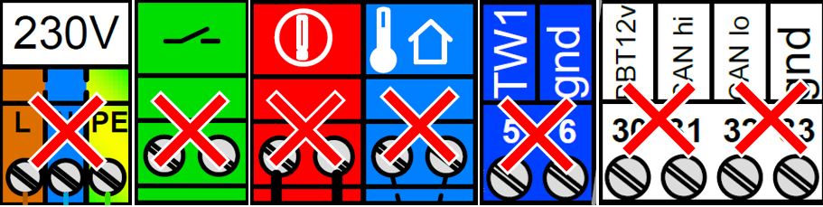
DO NOT connect the Gateway to an on/off contact, an OpenTherm bus, a 24V or mains line! ONLY to an EMS bus connector. Do not connect the Gateway in series with other EMS devices, only in parallel. If you are unsure which connector to use, send me a picture and I’ll help you selecting the correct one.
Below some ‘forbidden’ connectors:
To use the screw terminal of the Gateway remove the top of the case to access the screw terminal by unscrewing the four case screws on the bottom.

It does not matter which EMS wire you connect to which terminal pin, as the Gateway has an internal correction circuit.
After you have connected the EMS bus wires and are sure it works properly you can screw the case top back again. If the Gateway is connected correctly, it will start blinking slowly to indicate it’s working and looking for the EMS bus and WiFi network.
Do not connect both the jack and the screw terminal at the same time. Both connectors are internally hardwired so by connecting both at the same time you can short circuit the bus.
First boot -> Check the LED
If you plug the Gateway into the boiler, the on-board LED will start to blink slow as a sign it has booted and looking for the EMS bus. As soons as it has discovered the EMS bus and your Wi-Fi network, it will light up solid. If the Gateway has already been configured before, the LED will light up solid really quickly after boot. But if it’s new and not connected to your WiFi network yet, it will continue to blink slowly.
The blink speed can be compared at this Youtube video of Gateway LED blink speed 1.
If it lights up solid, then go to Connecting the Gateway to your home network. If you don’t see any LED go to Troubleshooting.