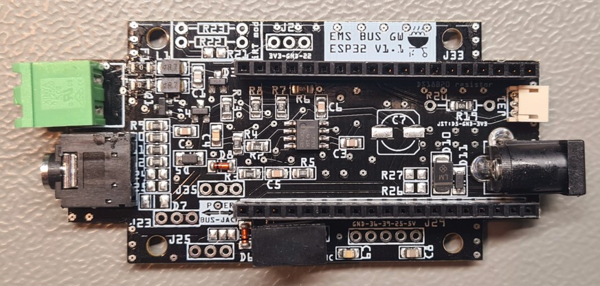
EMS Gateway base boards
S32 base board
The base board of the S32 Gateway is also sold seperate from the complete Gateway.

Features
The S32 base board provides the following features:
EMS to UART signal conversion for both RX and TX
EMS screw terminal and jack input
6-12V DC input with overvoltage protection
Built in high quality voltage regulator (Gaptec)
Connector for DS18B20 sensors
Additonal IO pins and 3V3, 5V and GND on headers
Compatible ESP32 board
The base board has two headers which are intended for the Ai-Thinker NodeMCU-32S microcontroller board. The antenna side of the NodeMCU-32S needs to point to the side of the green screw terminal.
Only this NodeMCU-32S will fit. There are quite some boards that look exactly like the NodeMCU-32S board (like the DevKit-C) but they are too wide.
You can however use other ESP32 boards but then you have to use Dupont wires to connect the ESP32 board to the base board. You can even use non-ESP type microcontrollers like Arduino and Raspberry Pi.
Loading the firmware
To load the firmware check the firmware installation instructions. When you load the firmware all default settings are already based on the S32.
Power options
To power the base board you have three options:
Power via the jack cable
Power via the DC barrel jack
USB power via the connector on the NodeMCU module.
If you connect the EMS bus to the green terminal block, you need to use an external power supply like 12V DC or USB. If your boiler has a service jack you can plug in this board with a 3.5mm stereo jack cable. No further power is needed as the jack provided 8,5 to 12 V DC to the board.
See also Powering a Gateway.
Voltages on the board
5 Volt DC
There is a high quality buck type voltage regulator on the board. This one is used to make 5V from either the DC barrel jack or from the service jack. When you use USB power then it’s not used. 5V is not used to power the base board itself.
3,3V DC
The entire base board runs on 3,3V. This is normally supplied via the 3V3 regulator on the NodeMCU-32S. If you do not use this microcontroller board, then you need to supply the base board with 3,3V.
5V DC is an input for the NodemCU-32S and 3,3V is an output from the NodeMCU-32S to the base board.
Pinout
Pinout DS18B20 header
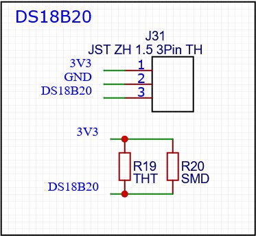
The 3 pin JST ZH 1.5mm header provides a connection for DS18B20 sensors. There is already a 4k7 Ohm pullup resistor on the base board.
The pinout should be viewed from the top side with the DS18B20 connector on the right side.

See also Adding external temperature sensors.
iRT modification
This board can also be modified so it can be used with iRT boilers. You need to remove R5 and place a 1.5MOhm resistor on R22 or R21. And use a Wemos ESP8266 microcontroller.
