Connecting a Gateway Premium II (P2)
Gateway connectors
The Gateway Premuim II (P2) has three connectors:
EMS bus screw terminal
3,5mm EMS service jack connector
JST connector
The latest Gateway boards also have an additional reboot button next to the JST connector.
Preferred order of connection
In short this is the best order in which you should try to connect the Gateway:
Service jack (If your boiler has one).
If you have a solar or mixer module with a bus OUT: EMS bus wires on EMS OUT terminal of the module.
If you don’t have an external module use the same EMS bus terminal as to which the thermostat is connected or should be connected to.
External USB adapter.
The service jack provides enough power for the Gateway.
The EMS bus wires might not be able to supply enough power when there are too many devices on the bus. In case the thermostat gives an error or you see intermittent errors on the display of the boiler, try a USB adapter. If the errors go away, there is not enough power on the EMS bus wires and you have to continue to use the USB adapter.
Service jack

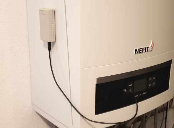
With the supplied jack cable you can plug in the Gateway to the service jack of the boiler. The entire device is powered via this service jack. So no additional power supply needed. Just the jack cable is all you need. First plug in the cable to the Gateway and then into the boiler. If the Gateway is plugged in, it will start blinking slowly to indicate it’s working and looking for the EMS bus and WiFi network.
Note
If you plug in or unplug the jack cable from the Gateway first instead of the boiler side, you may momentarily shortcut the boiler. It will then reboot, which can cause some clicking noises. Nothing to worry about but just unplug the boiler side first.
EMS/thermostat wires
If your boiler does not have a service jack or it does but you want to mount the EMS Bus Gateway elsewhere you can use the screw terminal to connect to the two EMS bus wires. This can be in parallel with the thermostat or from inside the boiler.
The latest Gateway version has a green external screw terminal. All older Gateways have a blue or black screw terminal inside the enclosure.
To use the screw terminal of an older Gateway remove the top of the case to access the screw terminal by unscrewing the four case screws on the bottom.

It does not matter which EMS wire you connect to which terminal pin, as the Gateway has an internal correction circuit.
You can see here how to locate the correct EMS bus terminals on your boiler: Connecting the Gateway to the boiler side.
After you have connected the EMS bus wires and are sure it works properly you can screw the case top back again. If the Gateway is connected correctly, it will start blinking slowly to indicate it’s working and looking for the EMS bus and WiFi network.
Do not connect both the jack and the screw terminal at the same time. Both connectors are internally hardwired so by connecting both at the same time you can short circuit the bus.
Power source selection
The Gateway Premium II can be powered via the service jack or the EMS bus itself. And also via a USB adapter.
Board version 1.6/1.7
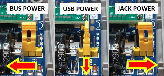
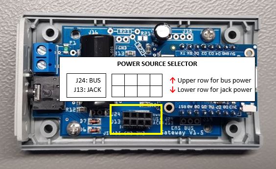
To switch between power sources you need to set the yellow jumper on the correct position. When the Gateway is delivered to you, jack power is selected. To make use of bus power instead, move the jumper to the upper position. When you are using the jack plug to connect the Gateway, but the jumper is on the EMS bus power header position, the Gateway will still draw its power from the EMS bus.

Board version 1.5
To switch between power sources you need to move the buck voltage regulator to a certain position on the header. When the Gateway is delivered to you, the buck is mounted on the (lower) service jack power header position. To make use of bus power instead, move the buck to the (upper) EMS bus power header position. When you are using the jack plug to connect the Gateway, but the buck is on the EMS bus power header position, the Gateway will still draw its power from the EMS bus.


Power considerations
The service jack on the boiler can provide more than enough power for the Gateway. The EMS bus itself however is limited in power. If you already have 2 or more devices (like thermostats, mixers) on the same EMS bus, there might not be enough power left for the Gateway. In case f.i. the thermostat doesn’t function properly after connecting the Gateway, you need to connect the Gateway via the service jack or use an external USB adapter (see below).
In case you have a mixer or solar module with a bus IN and bus OUT, try connecting the Gateway to the OUT terminal. This bus OUT is an internal power injector/bus repeater to add additional power on the bus. This can be used for the Gateway as well.
First boot -> Check the LED
If you plug the Gateway into the boiler, the on-board LED will start to blink slow as a sign its has booted looking for the EMS bus. As soons as it has discovered the EMS bus and your Wi-Fi network, it will light up solid. If the Gateway has already been configured before, the LED will light up solid really quickly after boot. But if it’s new and not connected to your WiFi network yet, it will continue to blink slowly.
The blink speed can be compared at this Youtube video of Gateway LED blink speed 1.
If the light is blinking slowly, then go to Connecting the Gateway to your home network. If you don’t see any LED go to Troubleshooting.