Description
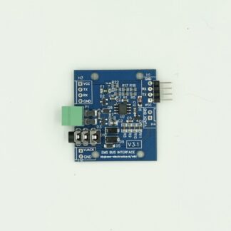
This is the latest update of the original BBQKees EMS bus to microcontroller UART interface board.
With this board you can safely connect a UART/serial port of your microcontroller or development board to the EMS bus.
No need to mess with soldering your own circuit just get this CE certified product here instead.
Features:
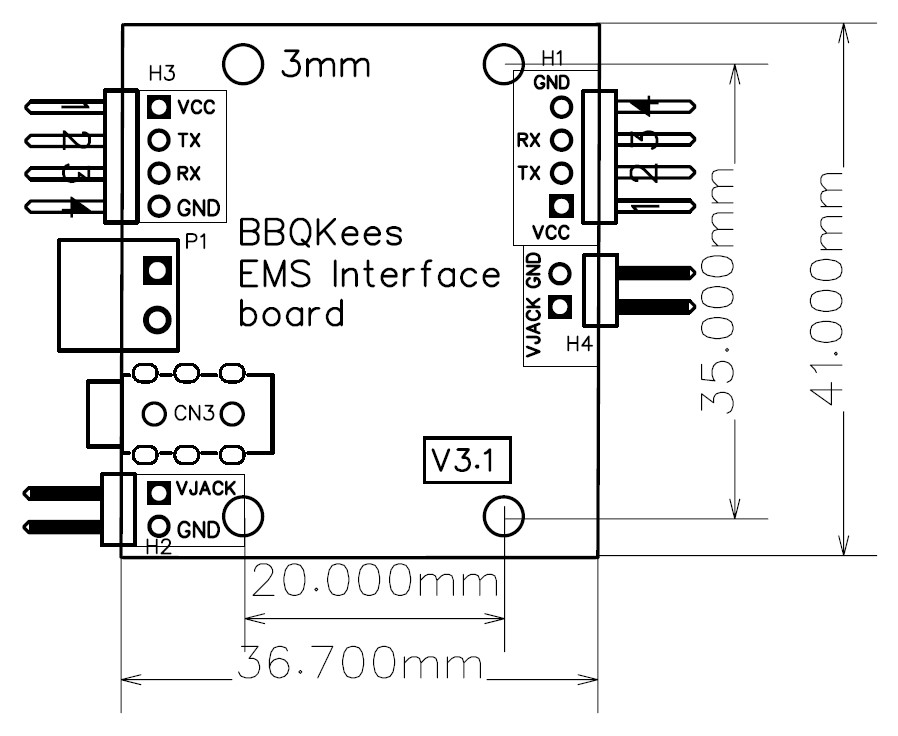
- Very small form factor (only 36x41mm)
- Robust bus-safe EMS interface design in operation all over Europe since 2018
- 3.3V and 5V UART/serial port compatible
- Third generation BBQKees EMS bus circuit for ALL boilers and heat pumps with an EMS bus
- Supports all EMS bus types and variations like EMS, EMS+, EMS2, Heatronic 3 etc.
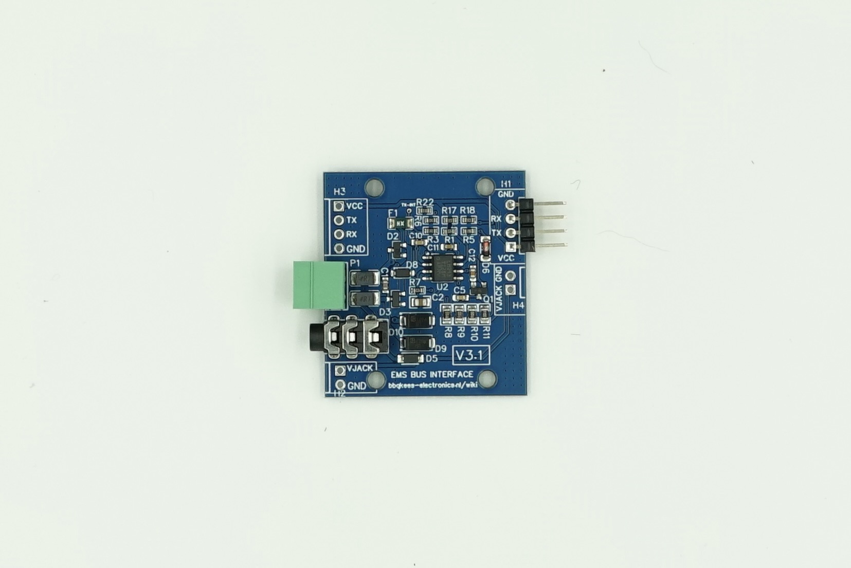
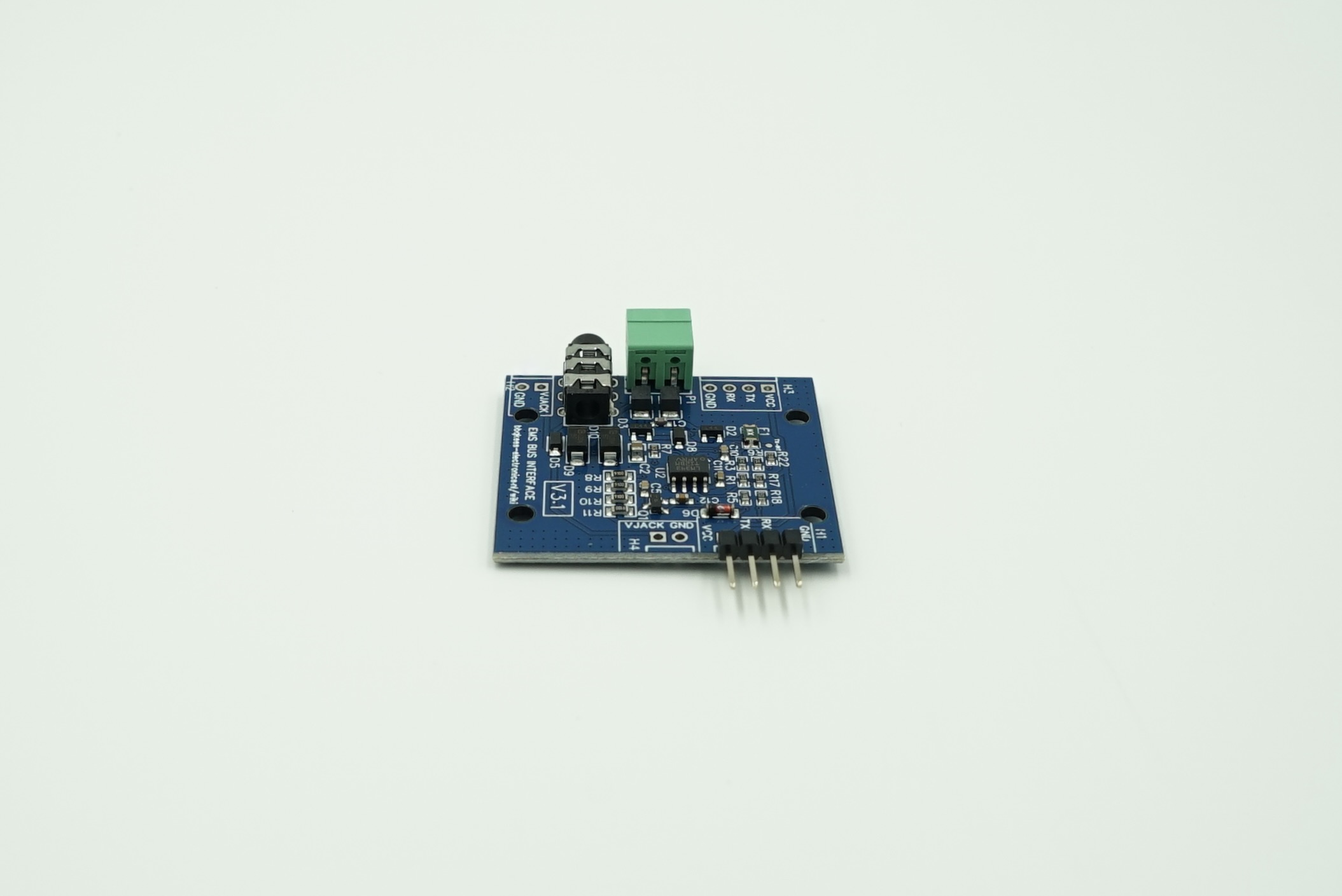
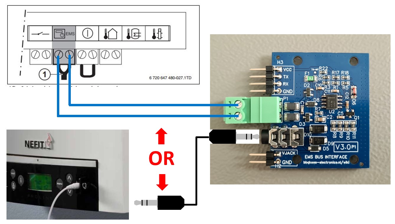
- Connect to the EMS bus via the screw terminal or the 3.5mm EMS service jack
- Connect to the UART via a 4 pin header
- Additional headers footprints for better customization and integration into your own design
- Additional bus protection with polyfuse and TVS diodes
- CE certified hardware
Options:
- 4 plastic PCB mounting feet (5mm height) with double sided tape
- High quality 50cm or 110cm EMS service cable for connecting the board to the EMS service jack on the boiler/heat pump (if applicable).
This cable has 2 extended plugs that fit into the recessed connector hole on the EMS boiler.
Because the EMS bus is about 16VDC, works with an offset and the signal in the top few volts, the RX signal needs to be stepped down to 0-3.3V or 5V.
TX works in the current domain so this board converts the TX signalling of the UART into a specific current signal for the EMS bus.
Did not understand anything what you just read?
That’s OK because the main reason I built this board is so you don’t have to worry at all about the electrical part of the EMS interface.
Just plug it into your favorite microcontroller and off you go.
The board is 3.3V and 5V UART compatible and works with all EMS, EMS+, EMS2 and Heatronic 3 and 4 boilers.
This board is compatible with f.i. every Arduino, Atmel, ESP8266, ESP32, NodeMCU-32S, DevKitC, Wemos, NodeMCU, Raspberry Pi and other microcontrollers.
For more information have a look at the product wiki.
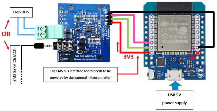
You can connect the board to the bus via the EMS service jack or via the EMS/thermostat wires on the screw connector.
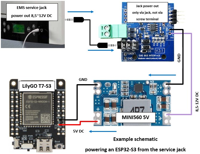
If you can use the service jack from the boiler or heat pump you can also power the microcontroller from the jack (8,5-12V DC via your own step-down voltage regulator). When you use the EMS bus wires you always need to power the microcontroller externally (F.i. with a USB power supply).
TIP: If you are going to buy a new ESP32 module to use with EMS-ESP32 it is advised to get an ESP32-S3 module with PSRAM.
Don’t bother connecting the EMS interface board to a, ESP8266, Pi or Arduino, there is no actual or updated software for it and writing it yourself is a lot of work.
So although this EMS interface board can interface with numerous different UARTs from various microcontrollers, it does not mean that there a a lot of code available online for every microcontroller architecture.
This board is NOT a substitute for the EMS Gateway!
This product is for those who like to play around with programming and microcontrollers.
It’s ONLY the hardware interface you need to interface with the EMS bus from a standard UART.
It does not come with any microcontroller or software.
You cannot power the microcontroller from the bus, only from the jack (8,5-12V DC available on the jack if connected).
If you have an old Nefit Ecomline, Buderus GB112 boiler or the control panel on your boiler looks like one of THESE, then your boiler is not EMS based but iRT. You cannot use this product with the IRT bus.
Also you cannot use this product with a Nefit Proline NxT as this is an OpenTherm boiler. The ‘regular’ Proline has EMS though.


19 reviews for EMS interface board V3.1
There are no reviews yet