updated: 25 March 2026 with new images on accessing the accessory connector.
To connect an EMS Gateway to a Heatronic 3 boiler like most Junkers, Worcester and some Bosch boilers you need to gain access to the EMS/BB screw terminal inside the boiler.
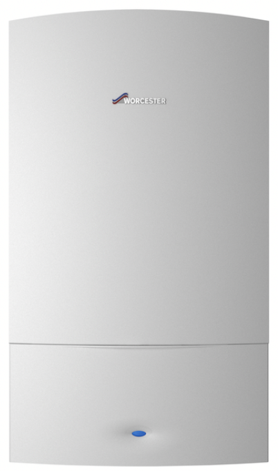
The guide is for all boilers that look like this:
Step one: disconnect the boiler from power
A critical first step is to unplug the boiler from mains power for safety.
Step two: unscrew and unhinge the front cover
There are small variations between these models but in general they are held by 3 or 4 screws. Two are located at the bottom near the front. One on the left and one on the right.
On the top of the boiler there are usually also one or two screws, although some covers are held by a just a clip.
You can unscrew all screws that are holding the metal front cover. Don’t worry it won’t fall off because it is still held by clamping.
Next you need to pull the underside forward and then slightly up and the whole cover will come off pretty easily. It only weighs a few kilo so it’s a simple one-person operation.


If it does not come off easily, there may still be a hidden screw somewhere so don’t use force and see if you missed a screw somewhere.
Step three: flip down the control panel
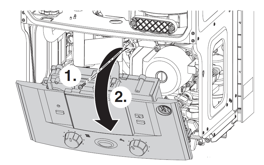
The control panel is held by a single screw on the top (nr. 1). Unscrew it and then you can flip down the control board.
Step four: Remove the connection cover
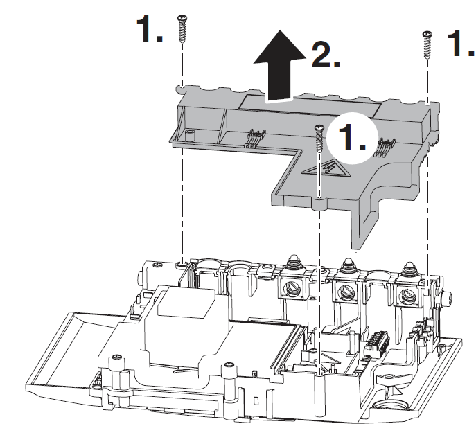
The connection cover is held by three screws. Unscrew them (nr. 1) and remove the cover.
Step five: Accessing the screw terminals on the control board
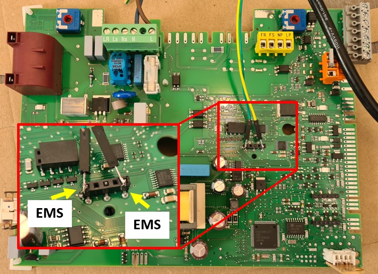
Now that the cover is off, you can access the EMS screw terminal marked ‘BB’ on the control board.
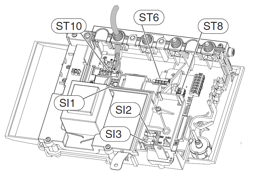
As mentioned above the EMS bus data lines are located on ST19 on the ‘BB’ terminal pins.
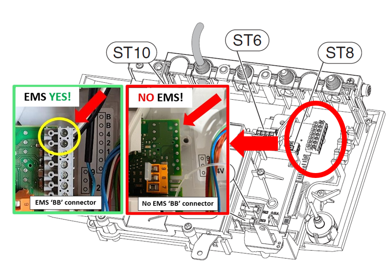
See if there is a grey screw terminal block mounted as above. If not, there is NO EMS bus on your boiler.
If there is a terminal block, please check if there is about 15V DC between the ‘BB’ pins. If so, you can go ahead and attach an EMS Gateway to these pins.
If there is nothing or only a few mV present, there is no EMS bus active on this port. You can look for it on another part of the circuit board. On Junkers boilers there is always an EMS bus present on the BB terminal.
For Worcester availability of the EMS bus on the BB pins depends on the specific boiler model and whether an integral diverter valve kit has been installed or not. For some boilers that don’t have an active EMS bus on the BB screw terminal it’s possible to swap out the code plug so it becomes active.
If you do not have an active EMS bus on the BB pins it may still be active on the accessory connector!
Accessing the accessory port
The front of the boiler has an mounting plate for an accessory. The connector for this accessory also has the EMS bus present.
You can slide the accessory cover upwards by pulling the pull tab on top of the cover. You can then pull the cover a bit forward and gently wiggle it out. The accessory connector has three gold plated contacts.


The outer two pins should have an active EMS bus.

If there is already an accessory mounted here, you can also access this connector on the other side of the circuit board to solder wires on. See the image below. Also see the wiki HERE.