Posted on

Using the Smart Grid (SG) and Photovoltaic (PV) function of your heat pump with the EMS Gateways

Input 4 options

Almost every Bosch/Buderus/Nefit heat pump with an EMS bus has 4 external inputs. These can be used to block the operation of the pump etc, but also for Smart Grid (SG) and Photo Voltaic (PV) features. You can virtually switch these inputs with all EMS Gateways to have the heat pump operate in a specific way.

Currently it’s a bit of a read and some trial and error but once set it will work automatically.

https://emsesp.org/tips-and-tricks/#automating-the-onoff-of-the-heat-pump-in-home-assistant

Every Bosch heat pump has 4 of these inputs, it depends on the country and your specific system but usually input 3 and/or 4 can be used for SG and PV.

You need to check the system menu or the installation manual of the heat pump to check which features are supported on which input. In the installation manual you can see which action the heat pump can do when one of these inputs is enabled. If you cannot find the information in the installation manual, you need to look up the manual for the controller/display of your unit (Likely the UI800 or HPC410).

The section you need to look up is called “Menu: External connections” and will look something like below.

If you ook into the following example of the installation manual of the Compress 6800i, then PV and SG are both on the input 4.

Heat pump External connections menu settings
Heat pump external connection feature table

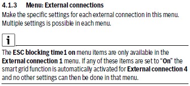
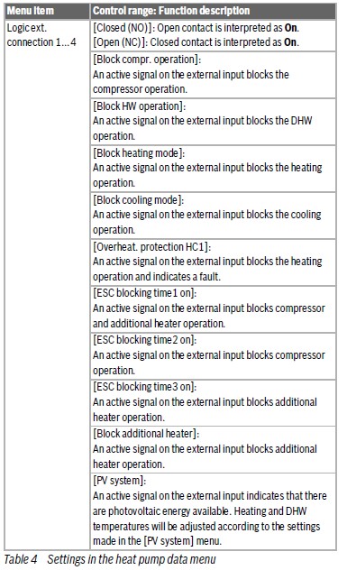
This menu will list all configurations that are possible to set for each input.
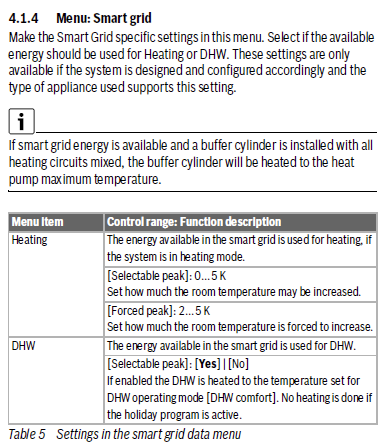
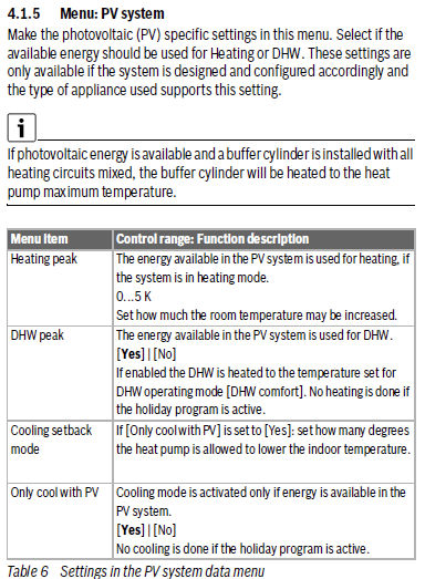
The Smart Grid and PV System menu are the most interesting.

Smart Grid settings Bosch heat pump
PV menu setting Bosch heat pump

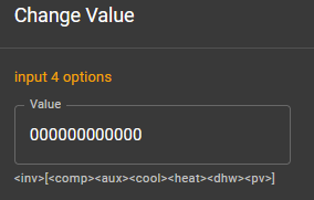
In the web interface of the Gateway you can see the input state of each input, and also the configuration of each input. In the example below the options for input 4.

Input 4 state
Input 4 options

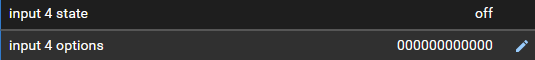
If you change the configuration the the menu to the SG and/or PV feature you want to activate, you can see the corresponding input values.

You can send these same values from Home Assistant to the Gateway to enable these features.

However, the heat pump expects the actual input to be enabled. But there is nothing physically attached to the inputs. But there is a workaround. The first bit of the configuration will tell the heat pump if the signal is active high, or active low.
So it should enable the function if the physical state of the input is ‘Normally Open’ and thus enabled when closed, or ‘Normally Closed’, and thus enabled when open. What we need is the second one. As the manual describes: “Open contact is interpreted as ‘ON’“.

If we invert the logic here, and attach and detach the configuration to the input every time we need it, you can turn on or off the PV and SG feature of your heat pump with your EMS Gateway.

You can use the same logic to activate the ‘EVU Sperre’ feature etc.

Posted on

Accessing the EMS/BB terminal on a Junkers or Worcester boiler (and some Bosch as well).

To connect an EMS Gateway to a Heatronic 3 boiler like most Junkers, Worcester and some Bosch boilers you need to gain access to the EMS/BB screw terminal inside the boiler.

The guide is for all boilers that look like this:

General fascia appearance of a Heatronic 3 style boiler

Step one: disconnect the boiler from power

A good first step is to unplug the boiler from mains power for safety.

Step two: unscrew and unhinge the front cover

There are small variations between these models but in general they are held by 4 screws. Two are located at the bottom near the front. One on the left and one on the right.

On the top of the boiler there are usually also two screws, although some covers are held by a clip.

You can unscrew all screws that are holding the metal front cover. Don’t worry it won’t fall off because it is still held by clamping.

Next you need to pull the underside forward and then slightly up and the whole cover will come off pretty easily. It only weighs a few kilo so it’s a simple one-person operation.
If it does not come off easily, there may still be a hidden screw somewhere so don’t use force and see if you missed a screw somewhere.

Step three: flip down the control panel

Flipping down the control panel on a Heatronic 3 boiler

The control panel is held by a single screw on the top (nr. 1). Unscrew it and then you can flip down the control board.

Step four: Remove the connection cover

Removing the connection cover on a Heatronic 3 boiler

The connection cover is held by three screws. Unscrew them (nr. 1) and remove the cover.

Step five: Accessing the screw terminals on the control board

Now that the cover is off, you can access the EMS screw terminal marked ‘BB’ on the control board.

The control board of a Heatronic 3 boiler

As mentioned above the EMS bus data lines are located on ST19 on the ‘BB’ terminal pins.

Finding the BB Screw terminal block on a Heatronic 3 control board

See if there is a grey screw terminal block mounted as above. If not, there is no EMS bus on your boiler. If there is a terminal block, please check if there is about 15V DC between the BB pins. If so, you can go ahead and attach an EMS Gateway to these pins. If there is nothing or only a few mV present, there is no EMS bus active on this port. You can look for it on another part of the circuit board. On Junkers boilers there is always an EMS bus present on the BB terminal.

For Worcester availability of the EMS bus on the BB pins depends on the specific boiler model and whether an integral diverter valve kit has been installed or not. For some boilers that don’t have an active EMS bus it’s possible to swap out the code plug so it becomes active.

If you do not have an active EMS bus on the BB pins it may still be active on the other side of the circuit board. See the image below. Also see the wiki HERE.

Alternative EMS bus location on Worcester circuit board